
Hydraulic interconnection type energy storage and feedback suspension and using method thereof

An interconnected, energy-feeding technology, applied in suspension, elastic suspension, transportation and packaging, etc., can solve problems such as unfavorable system energy recovery efficiency, unfavorable component service life, energy waste, etc., to improve energy-feeding efficiency, The effect of reducing fuel consumption and improving dynamic performance

Active Publication Date: 2016-02-03
JIANGSU UNIV
View PDF5 Cites 4 Cited by
  • Summary
  • Abstract
  • Description
  • Claims
  • Application Information

AI Technical Summary

Problems solved by technology

The spring has the characteristics of phase lag and "pass low frequency, block high frequency", and the inertial accumulator has the characteristics of phase advance and "pass high frequency, block low frequency". The impact and vibration caused by high speed are buffered and attenuated; due to the redundant constraints of the four-wheeled vehicle, the over-positioning is caused. On the rough road, the body will bear a large torsional load, which is not conducive to the service life of the parts of the body; the traditional suspension The vibration energy of the vibration is usually dissipated in the form of heat through the damper, resulting in a waste of energy, and the energy-feeding suspension can recycle this part, which is energy-saving and environmentally friendly.
Patent No. 201420027645.X utility model patent: an energy-feeding active suspension mainly involves the active control of the suspension to improve the ride comfort of the vehicle, but its high energy consumption is not conducive to the energy recovery efficiency of the entire system improvement

Method used


Image

  • Hydraulic interconnection type energy storage and feedback suspension and using method thereof

Examples


Embodiment Construction

[0017] The specific embodiments of the present invention will be further described below in conjunction with the accompanying drawings.

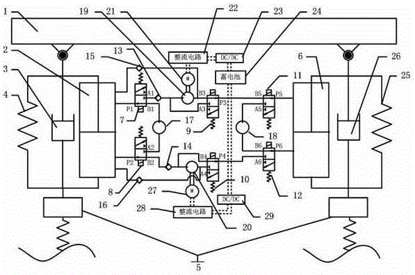
[0018] Such as figure 1 Shown: a hydraulically interconnected energy storage and energy feeding suspension includes sprung mass 1, hydraulic cylinder a2, hydraulic cylinder b6, shock absorber a3, shock absorber b26, spring a4, spring b25, unsprung mass 5, Solenoid valve a7, solenoid valve b8, solenoid valve c9, solenoid valve d10, solenoid valve e11, solenoid valve f12, one-way valve a13, one-way valve b14, one-way valve c15, one-way valve d16, hydraulic motor a17, hydraulic motor b18, hydraulic motor c19, hydraulic motor d20, rotating electrical machine a21, rotating electrical machine b27, rectifying circuit a22, rectifying circuit b28, DC / DC converter a23, DC / DC converter b29, storage battery 24.

[0019] The upper ends of the hydraulic cylinder a2, the spring a4 and the shock absorber a3 are connected in parallel to the sprung mass 1, a...


PUM


Abstract

The invention discloses a hydraulic interconnection type energy storage and feedback suspension and a using method thereof. An upper cavity and a lower cavity of a left hydraulic cylinder and an upper cavity and a lower cavity of a right hydraulic cylinder of the energy storage suspension are interconnected in the forward direction through an energy feedback hydraulic pipeline. When an automobile travels to a common road surface, the riding comfort is considered first, an interconnection energy feedback loop is closed by switching work oil ports of electromagnetic valves, and the suspension is a hydraulic energy storage suspension. When the automobile travels to a rugged road surface, the work oil ports of the electromagnetic valves are switched, the interconnection energy feedback loop is opened, excessive constraints are reduced, and thus the purpose of removing torsion loads of an automobile body is achieved. Meanwhile, reciprocating flow energy of the left hydraulic cylinder and the right hydraulic cylinder is recycled through the energy feedback hydraulic pipeline, and the energy is converted into electric energy to be used by automobile electrical equipment. The working performance of the suspension under multiple working conditions is effectively improved, energy recycling is achieved, and wide using prospects are achieved.

Description

technical field [0001] The invention relates to the technical field of vehicle suspensions, in particular to a hydraulically interconnected energy storage and energy feeding suspension and its use method. Background technique [0002] The proposal of the three-element ISD (inertia-spring-damping) suspension breaks through the limitations of the traditional electromechanical similarity theory and realizes the strict one-to-one correspondence between "mass-spring-damping" and "capacitance-inductance-resistance". The spring has the characteristics of phase lag and "pass low frequency, block high frequency", and the inertial accumulator has the characteristics of phase advance and "pass high frequency, block low frequency". buffer and attenuate the shock and vibration caused by high speed; the four-wheel vehicle has redundant constraints, resulting in over-positioning, and on rough roads, the body will bear a large torsional load, which is not conducive to the service life of th...

Claims


Application Information

Patent Timeline
IPC IPC(8): B60G17/0195B60G15/00
Inventor 汪若尘丁彦姝钱金刚陈龙
Owner JIANGSU UNIV
Learn More