Electrode for Electrochemical Reduction of Carbon Dioxide to Hydrocarbon and Its Preparation and Application

A hydrocarbon and carbon dioxide technology, applied in battery electrodes, circuits, electrical components, etc., can solve the problems of lower catalyst utilization rate and small specific surface area of ​​Cu nanoparticles, and achieve the effect of simple preparation method

Active Publication Date: 2018-06-08
DALIAN INST OF CHEM PHYSICS CHINESE ACAD OF SCI
View PDF2 Cites 0 Cited by
  • Summary
  • Abstract
  • Description
  • Claims
  • Application Information

AI Technical Summary

Problems solved by technology

Although the above electrode structure can improve the conversion rate of carbon dioxide to a certain extent, due to the small specific surface area of ​​Cu nanoparticles, and the electrode preparation process requires an additional binder, which reduces the utilization rate of the catalyst.

Method used


Image

  • Electrode for Electrochemical Reduction of Carbon Dioxide to Hydrocarbon and Its Preparation and Application
  • Electrode for Electrochemical Reduction of Carbon Dioxide to Hydrocarbon and Its Preparation and Application
  • Electrode for Electrochemical Reduction of Carbon Dioxide to Hydrocarbon and Its Preparation and Application

Examples


Embodiment 1

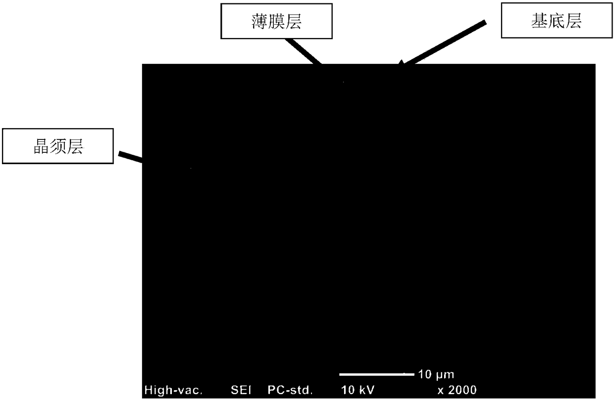
[0037]100um thick 0.3mm copper mesh (purity 99.99%) is used as the substrate. After degreasing treatment in acetone for 30min, at 4.0V voltage, 17.4M H in acidic solution 3 PO 4 Carry out activation treatment for 2min; take out the substrate after washing and drying in 0.01M CuSO 4 In the mixed solution of 0.5M lactic acid, treat it with -0.9V for 3min; after washing and drying, oxidize it at 500°C in an air atmosphere of 120ml / min for ~11h; in 1.0M H 3 PO 4 Reduction treatment was carried out at -3.0V for 10 min; after washing and drying, the prepared electrode was finally obtained. From figure 1 It can be seen that there is a layer of nanoparticles on the surface of the Cu mesh substrate, and a layer of nanowhiskers on the surface of the nanoparticle layer.

Embodiment 2

[0039] 100um thick 0.3mm copper mesh (purity 99.99%) is used as the substrate. After degreasing treatment in acetone for 30min, at 4.0V voltage, 17.4M H in acidic solution 3 PO 4 Carry out activation treatment for 4min; remove the substrate after washing and drying in 0.05M CuSO 4 In the mixed solution of 1M lactic acid, treat it with -1.2V for 3min; after washing and drying, oxidize it at 500°C in an air atmosphere of 120ml / min for ~11h; in 1.0M H 3 PO 4 Reduction treatment was carried out at -3.0V for 10 min; after washing and drying, the prepared electrode was finally obtained.

Embodiment 3

[0041] 1mm thick Cu plate (purity 99.99%) was used as the substrate, after degreasing treatment in acetone for 30min, at 3.0V voltage, 5M H in acidic solution 2 SO 4 Carry out activation treatment for 6 minutes; take out the substrate after washing and drying in 0.01M CuSO 4 In the mixed solution of 0.5M lactic acid, treat it with -0.9V for 3min; after washing and drying, oxidize it at 600°C for 8h in an air atmosphere of 130ml / min; in 1.0M H 2 SO 4 Reduction treatment was carried out at -3.0V for 10 min; after washing and drying, the prepared electrode was finally obtained.


PUM

PropertyMeasurementUnit
thicknessaaaaaaaaaa
thicknessaaaaaaaaaa

Abstract

The invention relates to an electrode for electrochemical reduction of carbon dioxide to prepare hydrocarbons and its preparation and application. The electrode consists of a base layer, a thin film layer composed of porous copper nanoparticles and an ordered layer; the outer surface of the flaky base layer is attached with A film layer composed of porous nanoparticles, with a copper whisker layer attached to the surface of the film layer composed of porous copper nanoparticles; the thickness of the base layer is 100-500 μm; the thickness of the porous nano-film layer is 100-200 μm; the thickness of the copper whisker layer is about 100nm ~ 500μm. The electrode with this structure effectively increases the reactive area, improves the mass transfer of reactants, and is beneficial to reduce the reaction polarization resistance and mass transfer polarization resistance, thereby improving the conversion efficiency of CO2; Regulation can improve the selectivity of ERC reaction products; this structure can improve the stability of Cu metal, thereby increasing the lifetime of ERC reaction catalysts.

Description

technical field [0001] The invention relates to an electrode structure for producing hydrocarbons by electrochemical reduction of carbon dioxide and its preparation and application, and belongs to the field of resource utilization of carbon dioxide. Background technique [0002] Energy is an important material basis for national economic development and people's lives. At present, my country's economy and society are in a stage of rapid development, and the demand for energy continues to increase. CO 2 Gas emissions are also increasing. According to the latest report of the International Energy Agency (IEA), the global CO 2 Emissions reached 31.6 billion tons; by 2030, annual carbon dioxide emissions are expected to increase to 43 billion tons, an increase of 60%. Therefore, how to reduce CO 2 emissions, effective use of CO 2 It has become a research hotspot in recent years. [0003] CO 2 There are three main methods of emission reduction and utilization: (1) capture ...

Claims


Application Information

Patent Timeline
Patent Type & Authority Patents(China)
IPC IPC(8): H01M4/86H01M4/88H01M4/90
CPCY02E60/50
Inventor 钟和香张华民毛景霞邱艳玲
Owner DALIAN INST OF CHEM PHYSICS CHINESE ACAD OF SCI
Why Eureka
Try Eureka