An energy-saving camera device
A camera device and camera technology, applied in circuit devices, battery circuit devices, image communication, etc., can solve the problems that the camera system cannot achieve omnidirectional scanning, affect the processing speed of the background computer, and have no responsiveness, so as to save and find useful The time and structure of information are simple, and the monitoring effect is good.
- Summary
- Abstract
- Description
- Claims
- Application Information
AI Technical Summary
Problems solved by technology
Method used
Image

Examples
specific Embodiment 1
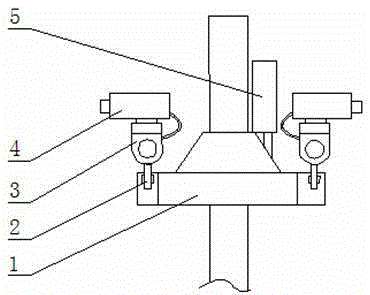
[0036] Such as figure 1 As shown, a kind of energy-saving camera device of the present invention comprises support 1, universal rotator 3, camera, control box 5; The support 1 is provided with the camera track that is ring or arc, and universal rotator 3 is arranged on On the camera track, the control box 5 controls the movement of the universal rotator 3 on the camera track and the rotation of the universal rotator 3 , the camera is connected to the universal rotator 3 , and the camera is electrically connected with the control box 5 .
[0037] More than two universal rotators 3 are arranged between the brackets 1, and each universal rotator 3 is connected to the control box 5 respectively; the control box 5 controls each universal rotator 3 to rotate independently and move independently on the camera track, The moving speed of the universal rotator 3 in the horizontal or vertical direction is 10-30r / min, and the moving speed of the universal rotator 3 on the camera track is ...
specific Embodiment 2
[0046] The control system of the energy-saving imaging device according to Embodiment 1 includes:
[0047] The control unit includes a control box 5, and the control box 5 is provided with an MCU, a memory, and an analog-to-digital converter; the analog-to-digital converter receives the analog signal of the camera and translates it into a digital signal, and sends the digital signal to the MCU, and the MCU extracts The data stored in the memory is compared with the newly received digital signal, and the action instructions stored in the memory are executed according to the comparison result; the time counter is simulated in the MCU, and the time counter is used to record time;
[0048] The camera unit includes a camera, a rangefinder, and a universal rotator 3. The camera adopts an autofocus system. The camera is a common infrared camera for AC and DC. The rangefinder is fixed on the camera side by side. Horizontal rotator and vertical rotator, horizontal rotator comprises the...
specific Embodiment 3
[0054] According to the control system of the energy-saving camera device of embodiment 2, its power supply control method:
[0055] (1) Set the analog time counter in the MCU and set the transformer switching time point, solar switching time point and flipping time point;
[0056] (2) When the light sensor detects that the light intensity is less than 1250Lx, the MCU controls the power supply from a step-down transformer with an output voltage of 12v, and reduces the lifting speed of the lifting device by 10%, the moving speed of the roller by 213%, and the universal rotation 314.6% rotation speed of the device;
[0057] (3) When the light intensity is 1250-1750Lx, the MCU detects that the signal intensity of the light sensor reaches the set value and at the same time simulates the time counter to reach the switching time point of the transformer. Side up; MCU control is powered by batteries and solar panels;
[0058] (4) When the light intensity is 1750-2800Lx, the MCU det...
PUM
 Abstract
Description
Claims
Application Information