Strong-focusing optical system used for composite machining of laser turning and grinding and machining method

A composite processing and optical system technology, applied in laser welding equipment, metal processing equipment, manufacturing tools, etc., can solve the problems of failing to specify the size of the focused spot, high processing accuracy requirements, and difficulty in the shape and size of the spot. Achieve the effect of being suitable for popularization, low cost, and ensuring processing efficiency and processing accuracy

Active Publication Date: 2016-02-17
HARBIN ENG UNIV
View PDF7 Cites 2 Cited by
  • Summary
  • Abstract
  • Description
  • Claims
  • Application Information

AI Technical Summary

Problems solved by technology

Publication No. CN101148002A proposes an optical focusing system for laser microprocessing machines, but it only proposes that the system has a better focusing effect, and fails to specify the size of the focusing spot; Herman et al. propose to use a rotating prism The light beam is generated, the structure is simple, and the energy utilization rate is high, but the disadvantage of this optical system is that the processing precision of the rotating prism aspheric mirror optical element is high, and it is difficult for the system to obtain the spot type and size required for processing.

Method used


Image

  • Strong-focusing optical system used for composite machining of laser turning and grinding and machining method
  • Strong-focusing optical system used for composite machining of laser turning and grinding and machining method
  • Strong-focusing optical system used for composite machining of laser turning and grinding and machining method

Examples


Embodiment Construction

[0023] Below in conjunction with accompanying drawing, the present invention is further described:

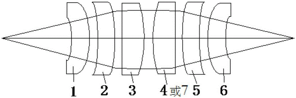
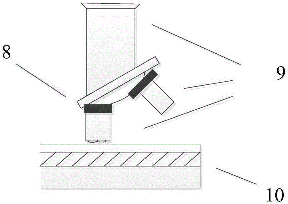
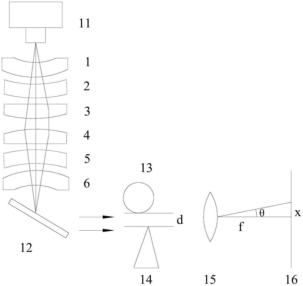
[0024] figure 1 Shows the design drawing of laser strong focusing optical system in the present invention, figure 2 The focusing optical path switching device is demonstrated, and the free conversion of circular light spot and linear light spot can be realized by rotating the lens barrel of the device. image 3 The diffraction measurement method of workpiece surface flatness in actual processing is shown.

[0025] figure 1 It shows the design diagram of the strong laser focusing optical system in the present invention, in which spherical mirrors and cylindrical mirrors are used for collimating and focusing design. Such as figure 1 The spherical mirrors 1, 2 and 3 shown are laser collimating parts. At present, there are two main types of industrial lasers used for laser processing: solid-state lasers and gas lasers. Among them, solid-state lasers are represented by Nd:YAG...


PUM

PropertyMeasurementUnit
diameteraaaaaaaaaa
widthaaaaaaaaaa
lengthaaaaaaaaaa

Abstract

The invention provides a strong-focusing optical system used for composite machining of laser turning and grinding and a machining method. The strong-focusing optical system comprises a collimating system and a focusing system and is characterized in that the collimating system is composed of three spherical mirrors; the focusing system is a round light spot focusing system composed of three spherical mirrors or a linear light spot focusing system composed of one cylindrical mirror and two spherical mirrors. A single beam of laser emitted by a laser device is focused into a round light spot through the strong-focusing optical system to irradiate the surface of a rotating workpiece, the workpiece rotates according to the specified rotating speed, the laser beam scans in the axial direction according to the specified speed, light energy of the laser beam is converted into heat energy, materials in a focus area on the workpiece are melted, gasified and thrown out, and a shaft part is machined in a turning manner. In order to increase the machining speed and improve the machining precision and the surface quality, the single beam of pulse laser emitted by the laser device is converted into a linear light spot to irradiate the surface of the turned workpiece in a focusing manner, and therefore ultrathin laser grinding is achieved.

Description

technical field [0001] The invention relates to a laser micromachining device, and also relates to a laser micromachining method. In particular, a strong focusing optical system and method for lathe turning and grinding. Background technique [0002] The cutting process of mechanical parts includes turning, milling, planing, grinding and so on. Traditional processing technology uses the forming movement of metal cutting machine tools to convert electrical energy into mechanical energy, and uses high-hardness metal cutting tools to apply cutting force to the workpiece, and cut off excess metal to shape the workpiece. The essence of cutting processing, one is to rely on the tool material to be harder than the workpiece material, and the other is to rely on cutting force to remove excess metal. However, with the development of cutting-edge scientific and technological products in the direction of high precision, high speed, high temperature, high pressure, high power, and min...

Claims


Application Information

Patent Timeline
Patent Type & Authority Applications(China)
IPC IPC(8): B23K26/073B23K26/064B23K26/36B23K26/38
CPCB23K26/0648B23K26/073B23K26/0738B23K26/36B23K26/38
Inventor 孙伟民李婉婷郭黎滨卢春莲麻镇宇耿涛段云菲
Owner HARBIN ENG UNIV
Why Eureka
Try Eureka