Pressure feed type high-pressure dense-phase pneumatic conveying device and pneumatic conveying method

A pneumatic conveying and pressure-feeding technology, applied in the field of powder material supply devices, can solve the problems of overall flow influence, low coal powder concentration, prone to failure, etc., to improve wear resistance and service life, gas-solid impact wear Reduce and avoid the effect of complex structure

Active Publication Date: 2016-02-24
SOUTHEAST UNIV
View PDF13 Cites 6 Cited by
  • Summary
  • Abstract
  • Description
  • Claims
  • Application Information

AI Technical Summary

Problems solved by technology

The disclosed technologies such as CN1274568C, CN101798022B, etc. all adopt the form of upper discharge, lower discharge or side discharge of the fluidized tank for high-pressure dense-phase pneumatic conveying. The delivery pipe must go deep into the fluidized area of ​​the tank, which has a certain impact on the overall flow in the tank; at the same time, because the delivery is in a fluidized state, the concentration of pulverized coal it transports is relatively limited. Hydrogenation process is not very suitable
CN1032746 adopts the sending tank in the form of lower discharge, but it is arranged with an air inlet around the conical discharge port. The size of the air injection has a great influence on the flow in the tank, which is not conducive to the stable control of conveying, and the concentration of pulverized coal is relatively high. Low
CN103213845A A star-shaped feeder is installed at the bottom of the material tank to control the material flow rate, which makes the power running parts added to the material delivery tank, which seriously affects the safety of the high-pressure system
GSP (Xu Zhengang, Gong Yuehua, Clean Coal Technology, GSP Pressurized Entrained Entrained Bed Technology and Its Application Prospect in China, Volume 4, Issue 3, P9-11, 1998) The coal supply device of the pressurized gasifier is in the tank The upper part of the output coal powder, but a stirrer is set at the bottom, and the rotating parts are set in the high-pressure equipment, which leads to complex structure, prone to failure, and affects the safety and reliability of the device

Method used


Image

  • Pressure feed type high-pressure dense-phase pneumatic conveying device and pneumatic conveying method

Examples


Embodiment Construction

[0023] The present invention will be further explained below in conjunction with the accompanying drawings.

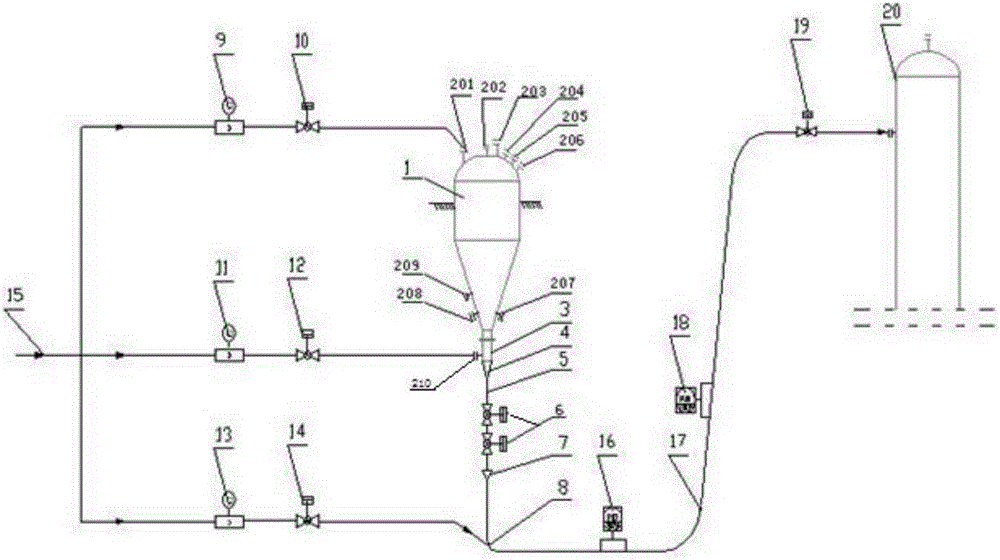
[0024] Such as figure 1 As shown, a pressure-feeding high-pressure dense-phase pneumatic conveying device includes a bottom-discharging delivery tank 1, and a pressure charging port 201, a powder inlet 202, Pressure relief port 203 , safety valve port 204 , nitrogen replacement gas pressure charging port 205 , nitrogen replacement gas pressure relief port 206 . The lower part of the main body of the delivery tank 1 is a cone bucket. In order to ensure the free downward overall flow of the powder in the delivery tank, the included angle of the busbar of the cone bucket is set at 15-45 degrees. A gas sampling port 207, a temperature measuring port 208 and a pressure measuring port 209 are provided on the side wall of the cone bucket.

[0025] The outlet of the lower cone bucket of the delivery tank 1 is connected to the vertically arranged first straight pipe section 3...


PUM


Abstract

The invention discloses a pressure feed type high-pressure dense-phase pneumatic conveying device and a pneumatic conveying method. Pressure feed type high-pressure dense-phase pneumatic conveying is adopted for providing a device and a method for supplying an ultra-concentrated-phase and high-stable-mass-flow-rate powder material; the structures of a conveying system and a material sending tank are greatly simplified; the shortcomings that a fluidization tank is complicated in form and structure, control requirements of fluidization wind in the tank are relatively high, a conveying tube is unfavorable to fluidization and overall flowing of powder in the tank and the like are avoided; investment is saved; meanwhile, the conveying device needs no power running member, so the safety of the high-pressure conveying device is guaranteed better. According to the conveying device disclosed by the invention, the gas-solid flow velocity is small; the gas-solid impact wear is greatly reduced; the wear resistance of the device is greatly improved; the service life of the device is greatly prolonged; the conveying device is stable, reliable and relatively good in regulation function, has the effect of avoiding the influences caused by unstable conveying to subsequent processes and especially has a more remarkable effect on a technique which requires high stability of subsequent processes of a pneumatic conveying terminal and ultrahigh concentration of coal dust.

Description

technical field [0001] The invention relates to a powder material supply device and method that utilizes pressure-feeding high-pressure dense-phase pneumatic conveying to provide super-dense phase and high stable mass flow rate, which is especially suitable for dry coal powder hydrogenation coal gasification, IGCC power generation, chemical industry , metallurgical flying, and other processing industries for powder material transportation. Background technique [0002] Pneumatic conveying device is a way to transport materials according to a specified route by means of gas energy (kinetic energy or static pressure energy) in the pipeline. Pneumatic conveying systems vary in type and structure due to different requirements. In recent decades, pneumatic conveying technology has developed extremely rapidly, especially with the development of dry coal powder pressurized gasification, hydrogasification, and IGCC technology, high-pressure dense-phase pneumatic conveying technolog...

Claims


Application Information

Patent Timeline
Patent Type & Authority Applications(China)
IPC IPC(8): B65G53/16B65G53/50B65G53/66
CPCB65G53/16B65G53/50B65G53/66
Inventor 熊源泉沈湘林周海军
Owner SOUTHEAST UNIV
Why Eureka
Try Eureka