Volatile organic compound online monitoring system
A volatile organic compound, monitoring system technology, applied in measurement devices, instruments, scientific instruments, etc., can solve the problems of low time resolution, late volatile organic compounds, complicated analysis process, etc., and achieve high time resolution, operation and maintenance. Low cost, high operability effect
- Summary
- Abstract
- Description
- Claims
- Application Information
AI Technical Summary
Problems solved by technology
Method used
Image
Examples
Embodiment 1
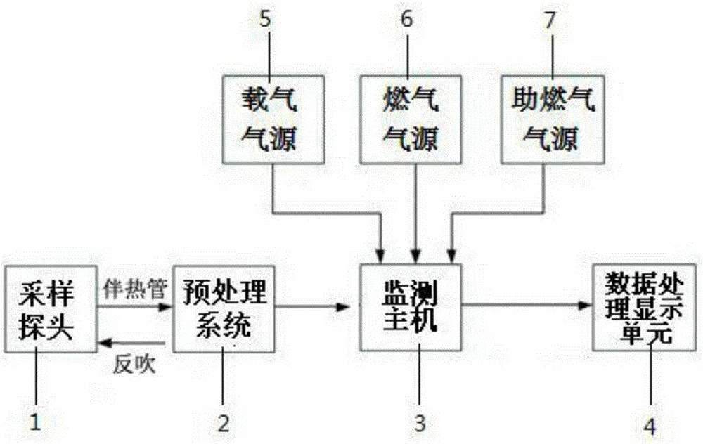
[0063] combine Figure 1-Figure 3 , this embodiment provides a system for online monitoring of volatile organic compounds, including: sampling probe 1, pretreatment system 2, monitoring host 3, data processing and display unit 4, carrier gas source 5, gas source 6, assisted gas The gas source 7, wherein the sampling probe 1 is used to collect the sample gas in the discharge pipeline of the fixed pollution source, the pretreatment system 2 is used to remove dust, dehumidify and flow control the sample gas, and the monitoring host 3 is used to separate and monitor the sample gas Detection, data processing and display unit 4 is used to process and calculate the signal output by the monitoring host 3, the carrier gas source 5 provides carrier gas for the monitoring host, the gas source 6 provides gas for the detector, and the gas-supporting gas source 7 is for detection The device provides assisted gas.
[0064] The sampling probe 1 is connected with the pretreatment system 2 thr...
Embodiment 2
[0105] refer to figure 1 , is a schematic diagram of the overall structure of the online monitoring system for volatile organic compounds according to the embodiment of the present invention, which includes a pretreatment system 2 , a monitoring host 3 , a data processing and display unit 4 , a gas source 6 , and a gas source 7 . The sampling probe 1, the heat tracing tube and the carrier gas source are connected externally. The sample gas is taken out from the discharge pipeline by the sampling probe 1, passes through the heating pipe to the pretreatment system 2, and enters the monitoring host 3 after dust removal, dehumidification and flow control. The output signal of the monitoring host 3 is processed and displayed on the data processing and display unit 4 .
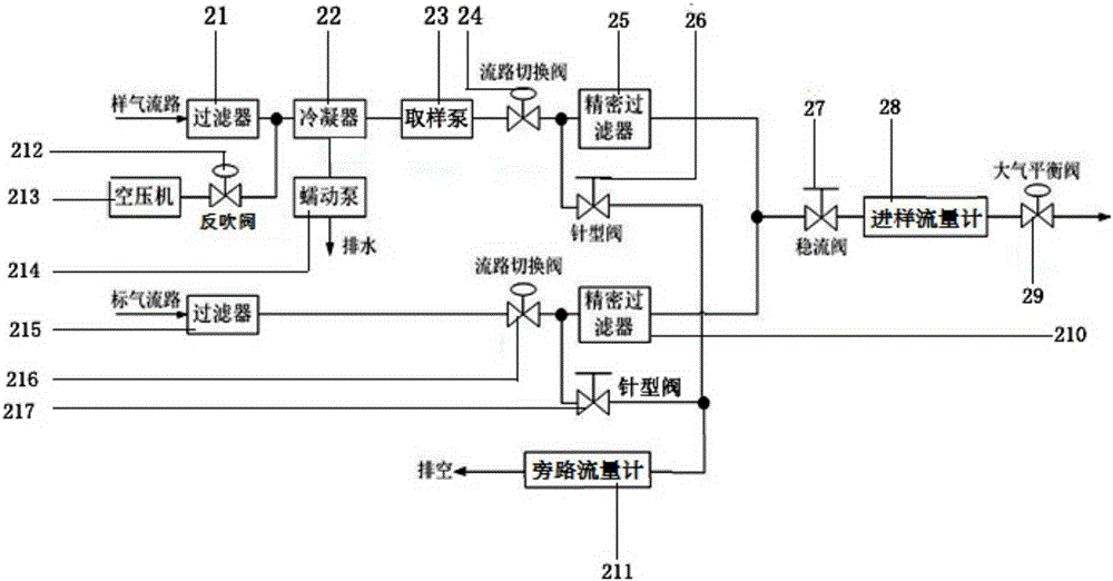
[0106] like figure 2 Shown is the workflow diagram of the pretreatment system. In the analysis state, the sampling pump 23 is turned on, and the sample gas enters the cabinet from the discharge pipeline through ...
Embodiment 3
[0110] On the basis of embodiment 1 and embodiment 2, this embodiment is an application embodiment:
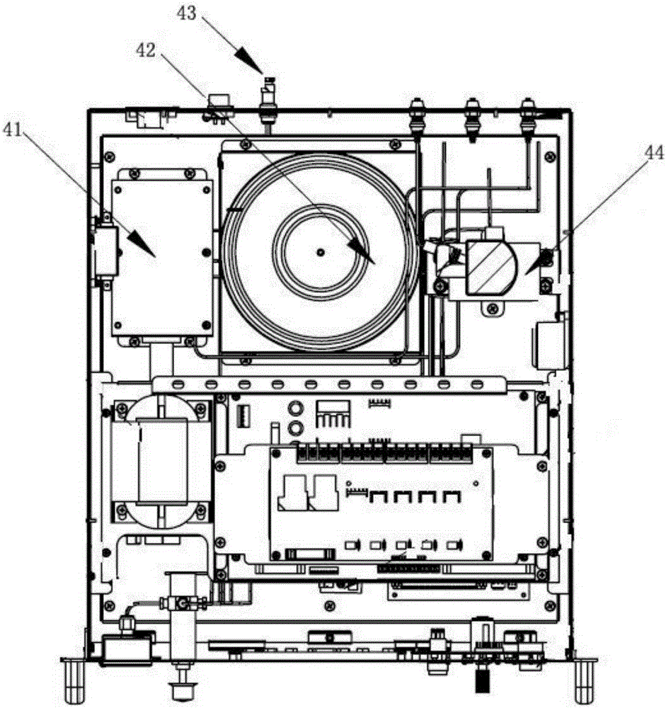
[0111] 1) Sampling, the pretreatment system 2 starts sampling, controls the electric multi-way valve 41 to be in the sampling state, and sends out a sampling signal at the same time. The air pump (sampling pump 23 ) in the pretreatment system draws the sample gas to be measured at the sampling probe 1 . The sample gas reaches the pretreatment system 2 through the heat tracing pipe, and the pretreatment system 2 performs dust removal, dehumidification and other treatments on the sample gas. Then fill the quantitative tube in the monitoring host 3 completely. After reaching the predetermined time, the pretreatment system 2 enters the sample injection state. After starting up, the software of the data processing and display unit 4 does not start to collect data, and is in the state of stopping collection. When receiving the sampling signal for the first time, the data processin...
PUM
 Abstract
Description
Claims
Application Information
 - R&D
- Intellectual Property
- Life Sciences
- Materials
- Tech Scout
- Unparalleled Data Quality
- Higher Quality Content
- 60% Fewer Hallucinations
Browse by: Latest US Patents, China's latest patents, Technical Efficacy Thesaurus, Application Domain, Technology Topic, Popular Technical Reports.
© 2025 PatSnap. All rights reserved.Legal|Privacy policy|Modern Slavery Act Transparency Statement|Sitemap|About US| Contact US: help@patsnap.com


