A Metal-polymer Composite Microstructure Heat Sink Structure for CPU Applications

A technology of composite microstructure and radiator, which is used in instruments, computing, electrical and digital data processing, etc., can solve the problems of poor radiator performance, affecting CPU performance, and high processing costs, to improve thermal conductivity, increase heat dissipation area, improve The effect of the flow situation

Active Publication Date: 2019-08-02
BEIJING UNIV OF CHEM TECH
View PDF8 Cites 0 Cited by
  • Summary
  • Abstract
  • Description
  • Claims
  • Application Information

AI Technical Summary

Problems solved by technology

Traditional cooling devices can no longer meet the requirements of efficient heat transfer, low cost and more complex and strict heat transfer environment
The current metal radiators are all optimized for CPU radiators by changing the structure and material of the radiator or increasing the volume of the radiator, but the current metal radiators have the problem that the heat conduction is greater than the heat dissipation, and the processing cost High, low efficiency, the existing water-cooled radiators have problems of leakage and blockage, and cannot be widely used in the field of CPU radiators
As we all know, in the CPU radiator, the performance of the radiator cannot be better improved by simply increasing the fan speed and optimizing the structure, and sometimes it makes the performance of the radiator worse.
The flow rate of gas in the bottom central area of ​​the ordinary flat CPU radiator is almost zero, so the air cannot conduct convective heat exchange with the bottom of the radiator directly in contact with the CPU. At this time, a high temperature area will be formed in this area, which will eventually affect the performance of the CPU. performance

Method used


Image

  • A Metal-polymer Composite Microstructure Heat Sink Structure for CPU Applications
  • A Metal-polymer Composite Microstructure Heat Sink Structure for CPU Applications
  • A Metal-polymer Composite Microstructure Heat Sink Structure for CPU Applications

Examples


Embodiment Construction

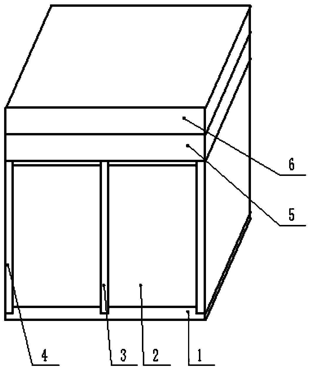
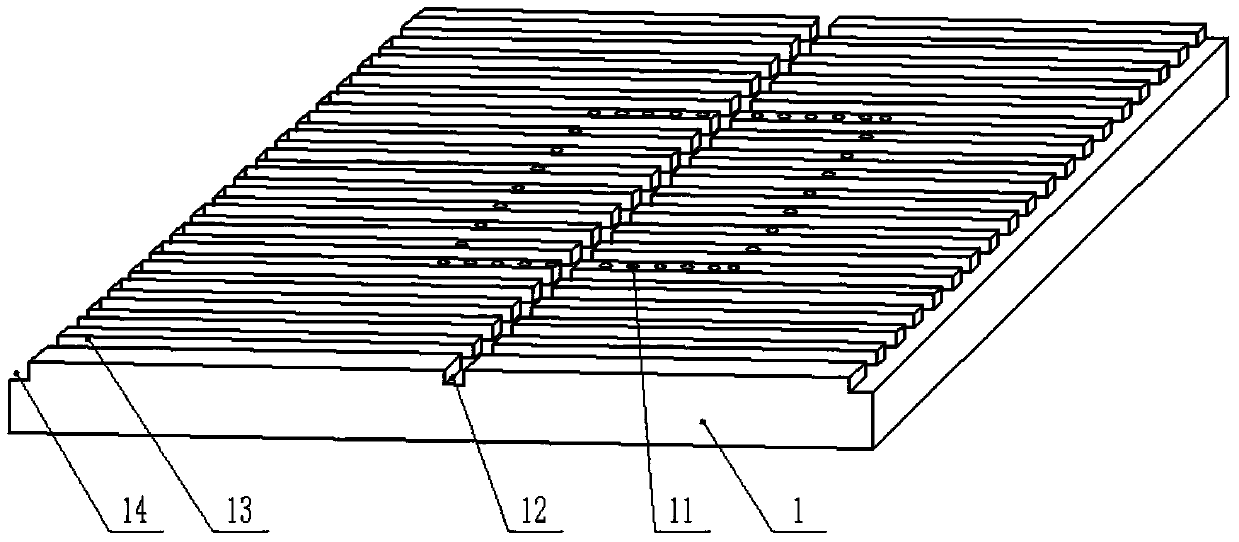
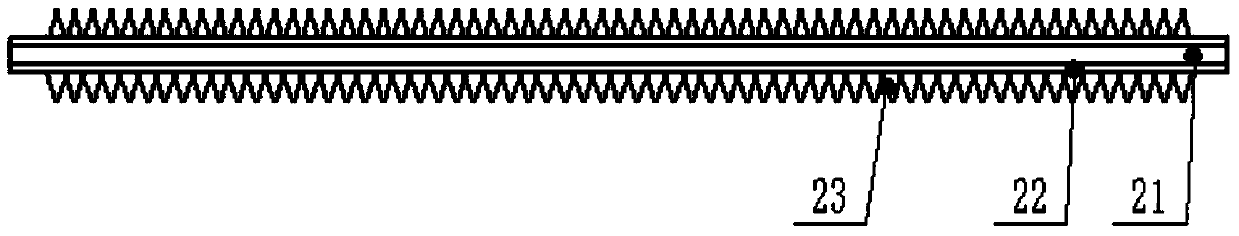
[0026]A CPU-oriented metal-polymer composite microstructure heat sink can be used for cooling the CPU. In this embodiment, the metal base plate 1 is a copper or aluminum cube base plate with a length, width and height of 795 mm. It is provided with multiple Install rectangular slots 13 with microstructured cooling fins, the size of which is 35mm2mmmm; the number of preferential rectangular slots is 32, and there are multiple rectangular slots 14 for installing metal side plates and for installing metal middle plates The rectangular groove 13, the size of the rectangular groove is 9mm3mmmm; a plurality of convection holes 11 on the metal base plate are arranged around the place in direct contact with the CPU, and the diameter of the convection holes 11 on the metal base plate is 5mm, uniformly distributed On a square 3mm larger in size than the CPU. The metal bottom plate 1 is pasted on the CPU through heat-conducting silicone grease, and fixed on the computer motherboard throu...


PUM


Abstract

The invention discloses a CPU application oriented metal-polymer composite micro-structure heat dissipator structure. The structure comprises a metal base plate, heat dissipation fins with a micro-structure, metal side plates, a metal medium plate, an air-inducing device and a fan. The metal base plate, the metal side plates and the metal medium plate are all provided with rectangular grooves of heat dissipation fins with the micro-structures. The metal side plate is externally coated with radiation protection paints, which effectively reduces an effect of components inside the case on the CPU heat dissipator. The heat dissipation fin with the micro-structure effectively increases heat dissipation area and improves radiation ability of the heat dissipator, thereby improving heat dissipation property. The air-inducing device may make the air passing through the fin more uniform, improving convection heat exchange ability. A convection hole on the metal side plate and a convection hole on the metal medium plate may make a temperature field and a speed field of the heat dissipator more synergistic, thereby improving the convection heat exchange ability. The heat dissipator structure of the present invention can effectively reduce CPU temperature, extend CPU service time, improve manufacturing efficiency, and save costs.

Description

technical field [0001] The invention relates to the heat dissipation structure design of a CPU, in particular to the background technology of a metal-polymer composite microstructure radiator for CPU applications. Background technique [0002] In today's highly competitive market, whether a low-cost, high-performance CPU cooler can be produced is related to the life and death of an enterprise. The heat sink is an important component of the computer, and the heat dissipation performance of the heat sink is related to the service life of the CPU. When the CPU is in use, it generates a certain amount of heat. If the heat is not dissipated in time, it will accumulate slowly and the heat will rise, causing the CPU components to burn out or reduce the service life. In recent years, the power of CPU chips has been increasing, and the calorific value has also been increasing, and CPU chips will develop towards miniaturization or miniaturization, and the size of CPU chips will conti...

Claims


Application Information

Patent Timeline
Patent Type & Authority Patents(China)
IPC IPC(8): G06F1/20
CPCG06F1/20G06F2200/202
Inventor 庄俭黄常清张亚军潘日
Owner BEIJING UNIV OF CHEM TECH
Why Eureka
Try Eureka