S-shaped-track-based multi-cavity electron accelerator

An electron accelerator and trajectory technology, applied in the direction of electrical components, accelerators, etc., can solve the problems of large radio frequency power loss of single-cavity accelerators and difficulty in increasing the beam current power of electron beams, so as to avoid cavity heating and deformation and reduce processing difficulty , the effect of small envelope

Active Publication Date: 2016-02-24
CHINA INSTITUTE OF ATOMIC ENERGY
View PDF5 Cites 9 Cited by
  • Summary
  • Abstract
  • Description
  • Claims
  • Application Information

AI Technical Summary

Problems solved by technology

[0003] The purpose of the present invention is to provide an electron accelerator with multiple resonant accelerating cavities to reduce the radio frequency power loss and improve the electron beam power of the linear accelerator, which is difficult to increase and the radio frequency power loss of the single cavity accelerator. Stability and reliability of transmission efficiency, electron beam beam power and accelerator operation

Method used


Image

  • S-shaped-track-based multi-cavity electron accelerator
  • S-shaped-track-based multi-cavity electron accelerator
  • S-shaped-track-based multi-cavity electron accelerator

Examples


Embodiment 1

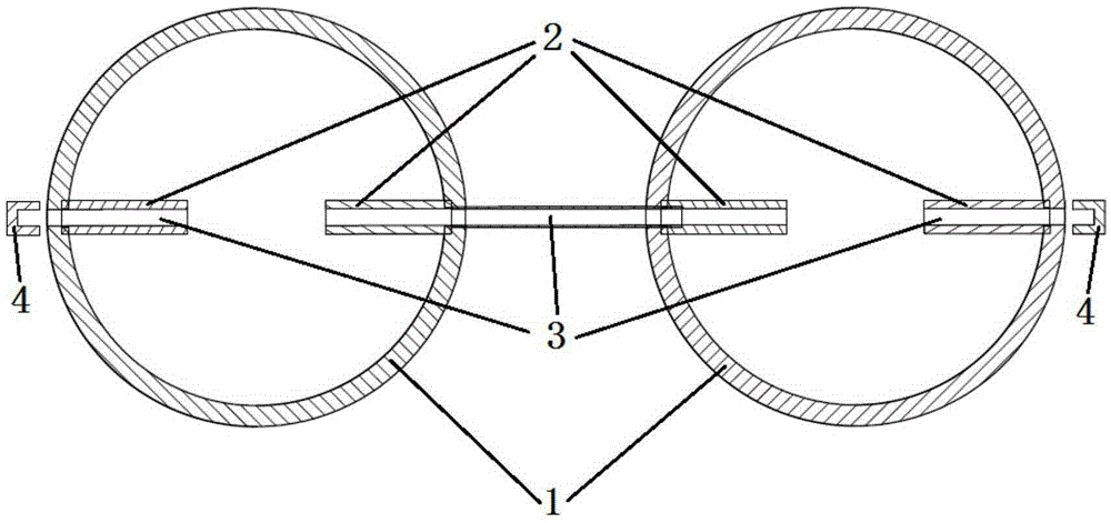
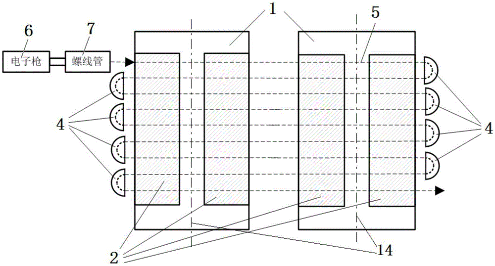
[0025] figure 1 , figure 2 What is shown is a serpentine trajectory accelerator using two resonant accelerating cavities, and the fundamental resonant frequencies of the cavities are both 100MHz. The diameter of the resonant accelerating cavity is about 1 meter, the length of the cavity is about 2 meters, the length of the electrode plate 2 is about 1.5 meters, and the axial distance between the two cavities is 1.5 meters. The electron beam is deflected 8 times on the same horizontal plane, and each linear movement is accelerated twice. The electron energy gain of each acceleration is 0.553MeV, and the distance between adjacent electron moving straight lines is 120mm.

[0026] The energy gain of the first and last acceleration of electrons in a cavity is the smallest, while the energy gain of the fifth acceleration is the highest, and the ridge electrode plate head 13 (such as Figure 5 The cancellation of shown) will lead to the deterioration of the inhomogeneity of the ac...

Embodiment 2

[0029] Image 6 , Figure 7What is shown is a serpentine trajectory accelerator using four resonant accelerating cavities, and the fundamental resonant frequencies of the cavities are all 200MHz. The cross-section of the resonant acceleration cavity is not a circle, but a square. The side length is about 0.5 meters, the cavity length is about 2 meters, the trapezoidal electrode plate 2 is about 1.5 meters long, and the axial distance between the two cavities is 0.75. Meter. The electron beam is deflected 8 times on the same horizontal plane, and each linear motion is accelerated 4 times. The electron energy gain of each acceleration is 0.276MeV, and the distance between adjacent electron motion straight lines is 120mm. The RF loss of a single cavity is 50kW, and the output electron beam energy is 10MeV.

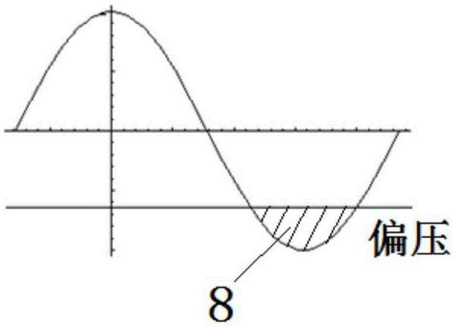
[0030] The gate-controlled electron gun structure adopts Figure 4 As shown, the gate control voltage waveform adopts image 3 shown. The voltage of the cathode of the ...


PUM


Abstract

The invention, which belongs to the technology of the accelerator design, particularly relates to an S-shaped-track-based multi-cavity electron accelerator comprising an electron gun, a solenoid, and at least two resonance acceleration cavities arranged side by side. One pair of electrode plates not containing electrode heads is arranged inside each resonance acceleration cavity; the electrode plates are arranged on an S-shaped motion plane of an electron beam current, wherein the moving direction of the electron beam current is perpendicular to the cavity axis direction of the resonance acceleration cavity; and beam current hole channels where electron beam currents pass are arranged inside the electrode plates. A plurality of deflection magnets are arranged at positions, corresponding to the electrode plates, of the two sides of the resonance acceleration cavities arranged side by side and enable the electron beam currents to deflect at 180 degrees; and directions of adjacent two-times deflection the electron beam currents are opposite to each other to form an S-shaped motion track. The processing difficulty is low; the efficiency of conversion from a radio frequency power to a beam power is high; and a beam power over 100kW can be obtained easily.

Description

technical field [0001] The invention belongs to the accelerator design technology, and in particular relates to a high-energy and high-power electron accelerator, which can be used in the fields of food and medical device irradiation, radiation chemical industry and the like. Background technique [0002] At present, there are two main types of high-energy and high-power electron accelerators used in the radiation processing industry: linear accelerators and single-cavity accelerators. The linear accelerator is divided into L-band and S-band, etc. The single-cavity accelerator is mainly the plum petal electron accelerator produced by IBA Company. Due to the limitation of the radio frequency power source and the accelerating structure, it is difficult for the linear accelerator to increase the power of the 10MeV electron beam to more than 50kW. Although the plum petal electron accelerator can obtain a 10MeV electron beam power of 200kW, the radio frequency loss on the inner ...

Claims


Application Information

Patent Timeline
Patent Type & Authority Applications(China)
IPC IPC(8): H05H7/00H05H7/18
CPCH05H7/00H05H7/18
Inventor 李金海王红英李春光王思力
Owner CHINA INSTITUTE OF ATOMIC ENERGY
Why Eureka
Try Eureka