Ag alloy sputtering target

A sputtering target and alloy technology, which is applied in sputtering plating, metal/alloy conductors, metal material coating processes, etc., can solve the problems of improving the yield of organic EL components, and achieve the suppression of abnormal discharge and sputtering. , the effect of high reflectivity and excellent heat resistance

Active Publication Date: 2016-03-02
MITSUBISHI MATERIALS CORP
View PDF8 Cites 3 Cited by
  • Summary
  • Abstract
  • Description
  • Claims
  • Application Information

AI Technical Summary

Problems solved by technology

[0015] Due to this problem, it cannot be said that the production yield of organic EL elements has been sufficiently improved, and further improvement is required.

Method used


Image

  • Ag alloy sputtering target
  • Ag alloy sputtering target
  • Ag alloy sputtering target

Examples


Embodiment

[0034] The manufacturing steps of the Ag-In alloy sputtering target of the present invention are as follows.

[0035] First, as raw materials for producing the Ag-In alloy sputtering target of the present invention, Ag with a purity of 99.99% by mass or more, In with a purity of 99.9% by mass or more, and Sb, Mg, Pd, and Cu with a purity of 99.9% by mass are prepared. and Sn.

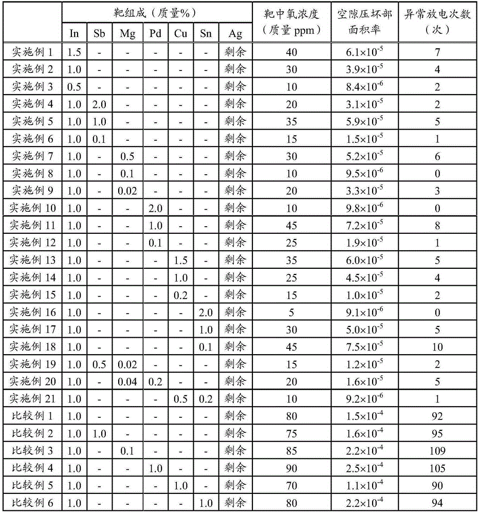
[0036] In the high-frequency vacuum melting furnace, as raw materials, Ag, In, and one or more selected from Sb, Mg, Pd, Cu, and Sn were loaded in the mass ratio shown in Table 1. The total mass at the time of melting was set at about 300 kg. After evacuating the vacuum chamber, Ar gas is replaced, Ag is melted, In is added to Ar atmosphere, and any element of Sb, Mg, Pd, Cu, and Sn is added, and the alloy molten metal is cast in a graphite mold. cast. Casting after melting is carried out by solidifying in one direction. This unidirectional solidification is carried out by pouring molten metal into ...


PUM

PropertyMeasurementUnit
areaaaaaaaaaaa
diameteraaaaaaaaaa

Abstract

The present invention provides an Ag alloy sputtering target by which it is possible to perform stable DC sputtering. This Ag alloy sputtering target contains 0.1-1.5 mass% In, the balance being a composition comprising Ag and unavoidable impurities, the concentration of oxygen being 50 mass ppm or less. In the entire area in the direction of thickness of the target, the proportion of area of a crushed void portion measured by an ultrasonic damage detection device is 1.0x10⁻⁴ or less in relation to the area of the sputtering surface.

Description

technical field [0001] The present invention relates to an Ag alloy sputtering target for forming a conductive film such as a reflective electrode film of an organic EL element or a wiring film of a touch panel, and particularly relates to a large-scale Ag alloy sputtering target having a large-area sputtering surface target. [0002] This application claims priority based on Patent Application No. 2013-150311 for which it applied in Japan on July 19, 2013, and Patent Application No. 2014-056037 for which it applied on March 19, 2014, and uses the content here. Background technique [0003] The organic EL element applies a voltage between the anode and the cathode formed on both sides of the organic EL light-emitting layer, injects holes from the anode and injects electrons from the cathode into the organic EL film, and utilizes the holes and electrons in the organic EL light-emitting layer. A light-emitting element based on the principle of emitting light when electrons co...

Claims


Application Information

Patent Timeline
Patent Type & Authority Applications(China)
IPC IPC(8): C23C14/34C22C5/06H01L51/50H05B33/10H05B33/24H05B33/26
CPCC22C5/06C22C5/08C23C14/3414H01B1/02
Inventor 野中庄平小见山昌三
Owner MITSUBISHI MATERIALS CORP
Why Eureka
Try Eureka