Surfacing welding method for abraded large roll shaft

A roll shaft, large-scale technology, applied in the direction of welding medium, welding equipment, welding equipment, etc., can solve the problems of local strength change roll wear, failure to achieve the original performance, uneven roll hardness, etc., to achieve suitable welding current, chemical The composition and performance are uniform, and the effect of fewer defects in the surfacing layer

Active Publication Date: 2016-03-09
JIANGSU JINHANG MACHINERY MFG CO LTD
View PDF8 Cites 17 Cited by
  • Summary
  • Abstract
  • Description
  • Claims
  • Application Information

AI Technical Summary

Problems solved by technology

[0002] During the use of large-scale roll shafts, due to large local strength changes, the rolls will be damaged, such as wear, collapse, cracks on the surface of the roll, breakage of the roll, uneven hardness of the roll, etc., which will lead to the scrapping of the roll, especially in cold rolling mills. This phenomenon often occurs in continuous casting steel plants
Because the rollers are made of special steel, and the special steel is manufactured through forging and complex heat treatment process, the price is relatively high, and the annual loss of the rollers in the steel mill is huge, and then it cannot be repaired or cannot be repaired. It was scrapped because of its original performance, which caused great economic losses to my country's metallurgical industry.

Method used


Image

  • Surfacing welding method for abraded large roll shaft
  • Surfacing welding method for abraded large roll shaft
  • Surfacing welding method for abraded large roll shaft

Examples


Embodiment Construction

[0032]Below in conjunction with accompanying drawing, the present invention is described in detail.

[0033] In order to make the object, technical solution and advantages of the invention clearer, the present invention will be further described in detail below in conjunction with the accompanying drawings and embodiments. It should be understood that the specific embodiments described here are only used to explain the present invention, not to limit the present invention.

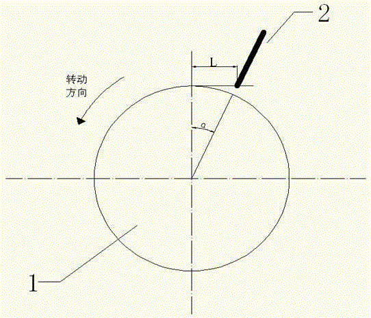
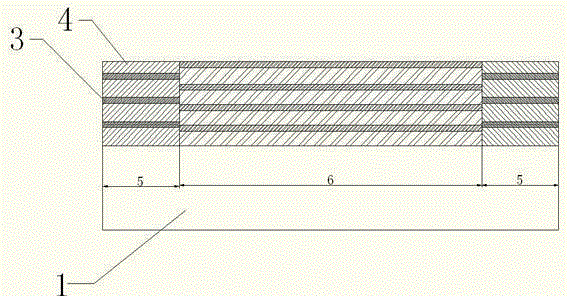
[0034] An embodiment of the present invention, such as figure 1 As shown, 1 is the roller axis, 2 is the welding wire, α is the forward inclination angle, the angle is 6°, L is the distance between the welding wire and the highest point of the roller axis, and the size is 25mm, 3 is the welding bead, and 4 is the overlap between the welding bead Part 5 is surfacing welding at the end of the roller shaft, and 6 is surfacing welding at the middle part of the roller shaft. The steps of the surfacing welding ...


PUM

PropertyMeasurementUnit
diameteraaaaaaaaaa
diameteraaaaaaaaaa
diameteraaaaaaaaaa

Abstract

The invention discloses a surfacing welding method for an abraded large roll shaft. The surfacing welding method is characterized by comprising the following steps that 1, preweld material analysis is carried out, preweld cleaning is carried out on the roll shaft, and preweld preparation is carried out; 2, after preweld preparation is finished, preweld preheating is carried out; 3, after preweld preheating is finished, automatic submerged arc welding is adopted for surfacing welding; 4, after surfacing welding is finished, welding slag is broken down, and postweld heat treatment is carried out; and 5, after heat treatment is finished, finally machining is carried out according to requirements. After the surfacing welding method is adopted, surfacing welding layer defects at the surfacing welding position are few, and the forming quality of a welding channel is good; the hardness of the surfacing welding position is distributed in a ladder manner from low to high from inside to outside, and the hardness of the outermost layer even ranges from 55 HRC to 60 HRC; the impact toughness and strength of the surfacing welding position are equal to those of the roll shaft and even exceed those of a base material by 1-2 times; the capacity for resisting spalling fatigue damage is high, the surfacing welding effect is remarkable, and the welding quality requirement can be completely met; and the whole surfacing welding process is easy to master and control, and good economical efficiency is achieved.

Description

technical field [0001] The invention relates to a welding process, in particular to an automatic submerged arc surfacing welding method after a large roller shaft is worn. Background technique [0002] During the use of large-scale roll shafts, due to large local strength changes, the rolls will be damaged, such as wear, collapse, cracks on the surface of the roll, breakage of the roll, uneven hardness of the roll, etc., which will lead to the scrapping of the roll, especially in cold rolling mills. This phenomenon often occurs in continuous casting steel plants. Because the rollers are made of special steel, and the special steel is manufactured through forging and complex heat treatment process, the price is relatively high, and the annual loss of the rollers in the steel mill is huge, and then it cannot be repaired or cannot be repaired. It was scrapped because of its original performance, which caused great economic losses to my country's metallurgical industry. Conten...

Claims


Application Information

Patent Timeline
Patent Type & Authority Applications(China)
IPC IPC(8): B23K9/04B23K9/235B23K9/18B23K35/30
CPCB23K9/048B23K9/18B23K9/235B23K35/3086
Inventor 张荣斌
Owner JIANGSU JINHANG MACHINERY MFG CO LTD
Why Eureka
Try Eureka