Bending processing method for small-caliber thin-wall waveguide tube

A technology for bending and processing waveguides, which is applied to the field of bending processing of small-diameter thin-walled waveguides, can solve the problems of the inner wall of the waveguide, damage the surface quality, affect the electrical properties, etc., achieve good bending forming effect, reduce production cycle, The effect of a short melting time

Inactive Publication Date: 2016-03-16
CHENGDU JINJIANG ELECTRONICS SYST ENG
View PDF7 Cites 7 Cited by
  • Summary
  • Abstract
  • Description
  • Claims
  • Application Information

AI Technical Summary

Problems solved by technology

[0003] The single arc bending often adopts the plugging steel strip bending technology. The post-plugging steel strip bending technology needs to make a moderately thick steel strip and quench the steel strip to make the steel strip have excellent elastic and mechanical properties. The problem that the inner wall of the waveguide is easily scratched during the process of threading and drawing the steel strip, because the inner diameter of the R220 waveguide is too small, resulting in no repairability, this method cannot be realized when the E-plane and H-plane of the R220 waveguide are bent
Multi-arc bending adopts the technology of melting urea as filler and then bending. The main problems of bending waveguide with urea as filler are: poor strength, large deformation of waveguide section after processing, which affects electrical properties; melting of urea and after processing The dissolved urea in the waveguide pollutes the environment and cannot be reused; it is very difficult to dissolve the crystals after the urea in the waveguide dissolves. Currently, it takes more than 3 days for the short waveguide urea filler to dissolve, and the long waveguide dissolves for half a month, which seriously restricts the production progress. The consumption is also high; because the ammonia in urea and some alkaline substances corrode the inner wall of the waveguide and damage the surface quality

Method used

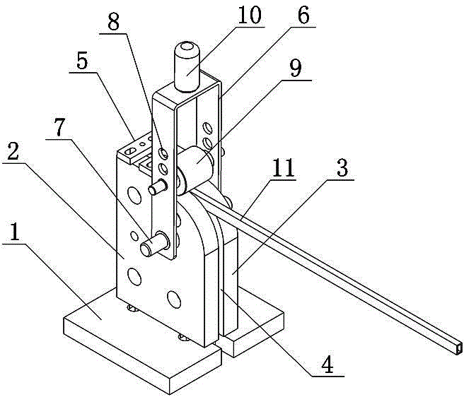
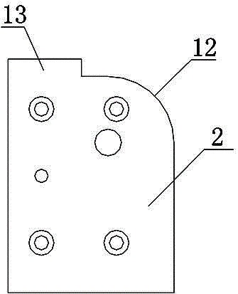
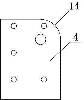

Image

  • Bending processing method for small-caliber thin-wall waveguide tube
  • Bending processing method for small-caliber thin-wall waveguide tube
  • Bending processing method for small-caliber thin-wall waveguide tube

Examples


Embodiment 1

[0030] A bending processing method for a thin-walled waveguide with a small diameter comprises the following steps:

[0031] S1, packing refining: including the following sub-steps:

[0032] S11, batching: batching each component according to the following parts by weight: Pb: 22 parts, Sn: 14 parts, Bi: 53 parts, Cd: 11 parts;

[0033] S12. Heating and smelting: Add the components in step S11 into the heating pot, heat and melt, and at the same time fully stir during the melting process, add mica flakes and rosin, the weight part of the mica is 1 part, the The weight part of rosin is 3 parts, remove impurities and metal oxides, select a container with a flat bottom in the molten state, and pour it into the container, before pouring the low melting point alloy in the molten state into the container, on the bottom and inner wall of the container Evenly apply a layer of engine oil, preferably 20# engine oil, cool and crystallize at room temperature to obtain low melting point a...

Embodiment 2

[0043] A bending processing method for a thin-walled waveguide with a small diameter comprises the following steps:

[0044] S1, packing refining: including the following sub-steps:

[0045] S11, batching: batching each component according to the following parts by weight: Pb: 25 parts, Sn: 12 parts, Bi: 50 parts, Cd: 13 parts;

[0046] S12. Heating and smelting: Add the components in step S11 into the heating pot, heat and melt, and at the same time fully stir during the melting process, add mica flakes and rosin, the weight of the mica is 1.2 parts, the The weight part of rosin is 2.5 parts, remove impurities and metal oxides, select a container with a flat bottom in the molten state, and pour it into the container, before pouring the low melting point alloy in the molten state into the container, on the bottom and inner wall of the container Evenly apply a layer of engine oil, preferably 20# engine oil, cool and crystallize at room temperature to obtain low melting point a...

Embodiment 3

[0056]A bending processing method for a thin-walled waveguide with a small diameter comprises the following steps:

[0057] S1, packing refining: including the following sub-steps:

[0058] S11, batching: batching each component according to the following parts by weight: Pb: 26 parts, Sn: 11 parts, Bi: 49 parts, Cd: 14 parts;

[0059] S12. Heating and smelting: Add the components in step S11 into the heating pot, heat and melt, and at the same time fully stir during the melting process, add mica flakes and rosin, the weight of the mica is 1.3 parts, the The weight part of rosin is 2.6 parts, remove impurities and metal oxides, select a container with a flat bottom under the molten state, and pour it into the container, before pouring the low-melting point alloy in the molten state into the container, on the bottom and inner wall of the container Evenly apply a layer of engine oil, preferably 20# engine oil, cool and crystallize at room temperature to obtain low melting point...


PUM

PropertyMeasurementUnit
melting pointaaaaaaaaaa

Abstract

The invention relates to a bending processing method for a small-caliber thin-wall waveguide tube, comprising the following steps: S1, filler refining: S11, material preparation: preparing the following components in parts by weight: 22-28 parts of Pb, 10-14 parts of Sn, 47-53 parts of Bi, and 11-15 parts of Cd; S12: heating for smelting: putting into a heating kettle for heating and smelting, sufficiently stirring during smelting, adding mica sheet and rosin, pouring into the container in molten state, and cooling for crystallization in room temperature to obtain low-melting-point alloy filler; S2, filler filling: S21, fixing a waveguide tube; S22, melting the low-melting-point alloy filler; S23, smearing machine oil; S24, filling; S3, bending formation; S4, filler recovery; S5, waveguide tube cleaning, thus obtaining the waveguide tube after bending formation. The bending processing method has the advantages of being short in production cycle, good in bending formation effect and recyclable in filler.

Description

technical field [0001] The invention relates to the technical field of bending forming of waveguides, in particular to a bending processing method of small-diameter thin-walled waveguides. Background technique [0002] The large-diameter waveguide currently used in the industry adopts the technology of filling the steel strip and then bending it for single bending. First, the steel strip is stuffed into the steel strip, and the waveguide is placed in the bending mold of the hydraulic press to bend it into a certain angle through the mold. Then pull out the strip. Multi-arc bending adopts the technology of melting urea as filler and then bending. Firstly, the urea is melted and filled into the waveguide solution tube, and then the waveguide is placed in the bending mold of the hydraulic press and bent into a certain angle by the mold, and then the cured Urine is removed from the waveguide. These two waveguide bending processes are mainly applied to waveguides with an inner ...

Claims


Application Information

Patent Timeline
Patent Type & Authority Applications(China)
IPC IPC(8): B21D9/15B21D9/16
CPCB21D9/15B21D9/16
Inventor 王展李益平杨芹粮胡平
Owner CHENGDU JINJIANG ELECTRONICS SYST ENG
Why Eureka
Try Eureka