Automatically-managed gear machining transmission system

A technology of automatic management and transmission system, which is applied in the field of automatic management of gear processing and transmission system, to achieve the effect of improving economic efficiency, simple structure and safe production management

Inactive Publication Date: 2016-03-16
CHONGQING GUANGDA MACHINERY FACTORY CO LTD
View PDF0 Cites 0 Cited by
  • Summary
  • Abstract
  • Description
  • Claims
  • Application Information

AI Technical Summary

Problems solved by technology

This kind of gear has high load-carrying capacity and efficiency, but it is not as easy to manufacture as the involute gear, and needs to be further improved

Method used


Image

  • Automatically-managed gear machining transmission system

Examples


Embodiment 1

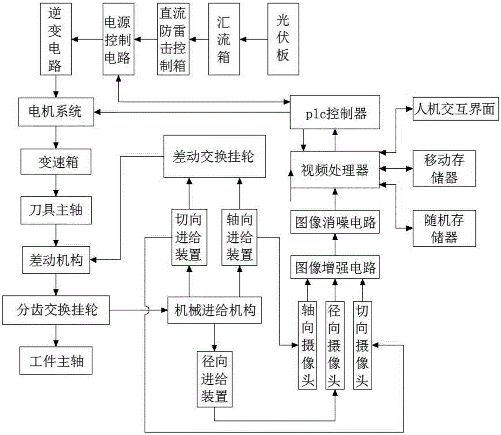
[0028] Automatically managed gear machining transmission systems such as figure 1 As shown, it is specially set up as the following structure: it is equipped with a control system, a motor system, a gearbox, a tool spindle, a differential mechanism, a split gear exchange hanger, a workpiece spindle, a differential exchange hanger, a mechanical feed mechanism and a feed system, the control system is respectively connected to the motor system and the feed system, the electrode system is connected to the gearbox, the output end of the gearbox is connected to the tool spindle, the tool spindle is connected to the differential mechanism, and the differential mechanism is connected to the branch The tooth exchange hanger, the divided tooth exchange hanger is respectively connected to the workpiece spindle and the mechanical feed mechanism, the mechanical feed mechanism is connected to the feed system, the feed system is connected to the differential exchange hanger, and the different...

Embodiment 2

[0035] This embodiment is further optimized on the basis of the above-mentioned embodiments. In order to better realize the present invention, the camera group can be used to process the radial feed device, axial feed device and tangential feed device. Take real-time shooting and provide data support for the formation of new adjustment strategies, such as figure 1 As shown, the following structure is particularly provided: the feed system is provided with a radial feed device, a tangential feed device and an axial feed device, and the mechanical feed mechanism is respectively connected with the radial feed device, The tangential feed device and the axial feed device are connected, and the tangential feed device and the axial feed device are connected with the differential exchange hanging pulley, and the camera group is connected with the radial feed device, the tangential feed device, and the tangential feed device respectively. It is connected to the feed device and the axia...

Embodiment 3

[0037] This embodiment is further optimized on the basis of the above-mentioned embodiments. Further, in order to better realize the present invention, multiple cameras can be used to process the radial feed device, the axial feed device and the tangential feed device respectively. The process is captured in real time and provides data support for the formation of new adjustment strategies, such as figure 1 As shown, the following structure is specially provided: an axial camera, a tangential camera and a radial camera are arranged in the camera group, and the axial camera, the tangential camera and the radial camera are all connected to the image enhancement circuit , the axial camera is connected to the axial feed device, the tangential camera is connected to the tangential feed device, and the radial camera is connected to the radial feed device.


PUM


Abstract

The invention discloses an automatically-managed gear machining transmission system. The transmission system is provided with a control system, a motor system, a gearbox, a cutter spindle, a differential mechanism, a tooth division change gear, a workpiece spindle, a differential change gear, a mechanical feeding mechanism and a feeding system. A plc, a video processor, an image enhancement circuit and a camera group which are sequentially connected are arranged in the control system. The transmission system further comprises a power supply system. A photovoltaic board, a combiner box, a direct-current lightning protection control box, a power control circuit and an inversion circuit which are sequentially connected are arranged in the power supply system. The inversion circuit is connected with the motor system. The power control circuit is connected with the plc and the working voltage is supplied to the video processor through the plc. Power is supplied through solar energy, so that non-renewable energy is effectively saved; and in the power supply process of the video processor, power is supplied and distributed through the plc, a power supply distributor is omitted, and meanwhile the video processor can be operated more stably.

Description

technical field [0001] The invention relates to the technical field of gear manufacturing, in particular to an automatic management gear processing transmission system. Background technique [0002] Gear, a mechanical element with teeth on the rim that continuously mesh to transmit motion and power. The application of gears in transmission has appeared very early. At the end of the 19th century, the principle of generative gear cutting method and special machine tools and cutting tools using this principle appeared one after another. With the development of production, the stability of gear operation was paid more attention. [0003] In the west, in 300 BC, the ancient Greek philosopher Aristotle, in "Mechanical Problems", just elaborated the problem of using bronze or cast iron gears to transmit rotary motion. The famous Greek scholars Aristotle and Archimedes have both studied gears. The famous Greek inventor Gutisibios evenly inserted pins on the edge of the circular pl...

Claims


Application Information

Patent Timeline
Patent Type & Authority Applications(China)
IPC IPC(8): B23F23/00B23Q5/28
CPCB23F23/00B23Q5/28Y02P70/10
Inventor 王彩虹
Owner CHONGQING GUANGDA MACHINERY FACTORY CO LTD
Why Eureka
Try Eureka