Space Beam Coupling System and Its Closed-loop Control Method

A technology of coupling system and spatial light detector, which is applied in the field of active spatial beam coupling system and its closed-loop control, can solve the problems of inability to realize precise automatic adjustment, difficult adjustment process, and poor environmental adaptability, so as to improve adjustment accuracy and Coupling efficiency, improved stability and environmental adaptability, and easy maintenance

Active Publication Date: 2018-07-27
西安中科聚能激光科技有限公司
View PDF5 Cites 0 Cited by
  • Summary
  • Abstract
  • Description
  • Claims
  • Application Information

AI Technical Summary

Problems solved by technology

However, due to the manual adjustment, there are defects such as low adjustment accuracy, difficult adjustment process, and the inability to realize precise automatic adjustment, and poor environmental adaptability, that is, when the external environment temperature and humidity of the laser change or the slight mechanical vibration is caused by transportation, the coupling system will be broken. To redo the manual calibration adjustment

Method used


Image

  • Space Beam Coupling System and Its Closed-loop Control Method
  • Space Beam Coupling System and Its Closed-loop Control Method
  • Space Beam Coupling System and Its Closed-loop Control Method

Examples


Embodiment Construction

[0032] In order to facilitate the understanding of the present invention, the present invention will be described more fully below with reference to the associated drawings. Preferred embodiments of the invention are shown in the accompanying drawings. The above are only preferred embodiments of the present invention, and are not intended to limit the patent scope of the present invention. Any equivalent structure or equivalent process conversion made by using the description of the present invention and the contents of the accompanying drawings, or directly or indirectly used in other related technical fields , are all included in the scope of patent protection of the present invention in the same way.

[0033]Unless otherwise defined, all technical and scientific terms used herein have the same meaning as commonly understood by one of ordinary skill in the technical field of the invention. The terminology used herein in the description of the present invention is only for t...


PUM


Abstract

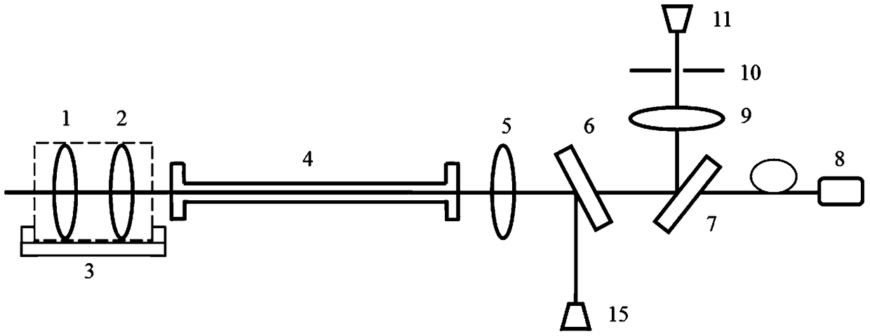
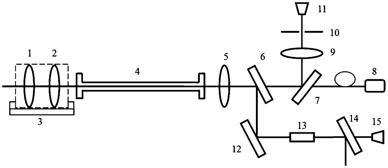
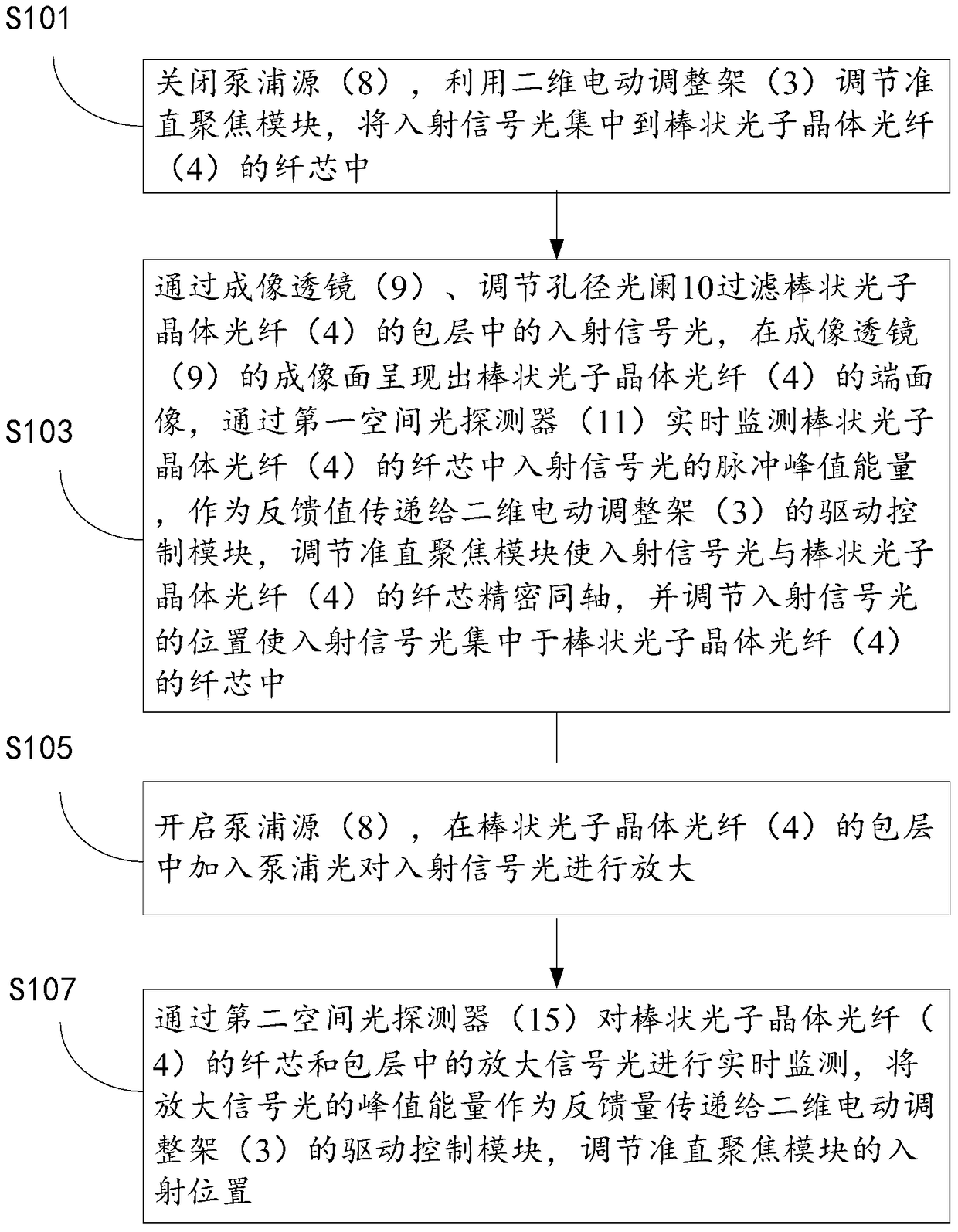
The invention provides a spatial beam coupling system. The system comprises a collimating and focusing module, an electric adjusting rack 3, a rod-like pohotonic crystal fiber 4, a convex lens 5, a first dichroic mirror 6, a second dichroic mirror 7, a pumping source 8, an imaging lens 9, a aperture diaphragm 10, a first spatial optical detector 11 and a second spatial optical detector 15, wherein the collimating and focusing module is arranged on the electric adjusting rack 3, and is orderly coaxial to the rod-like pohotonic crystal fiber 4, the first dichroic mirror 6 and the second dichroic mirror 7. The invention also provides a closed-loop control method of the spatial beam coupling system. The spatial beam coupling system can improve adjustment precision and coupling efficiency of spatial optical coupling, and when situations, such as temperature fluctuation and mechanical vibration, occur in environment, the spatial beam coupling system can execute active closed-loop control and perform fine adjustment to the collimating and focusing module, thus, complex manual calibration is avoided, and stability and environmental adaptability of the system are improved.

Description

technical field [0001] The invention relates to the field of laser technology, in particular to an active spatial beam coupling system and a closed-loop control method thereof. Background technique [0002] Ultra-fast laser micromachining utilizes a new type of "light energy" that interacts with materials without impact, without thermal effects, and ultra-fine and efficient cold processing mechanisms. It has non-contact, small thermal impact, high energy focus, easy operation, high flexibility, high efficiency, and With outstanding advantages such as quality, energy saving and environmental protection, it plays the role of an innovative pioneer, represents the development direction of advanced manufacturing, and leads manufacturing technology into a new era of laser manufacturing. High-energy ultra-fast femtosecond lasers have created a new field of ultra-fine, non-thermal damage and 3D space processing and processing of materials with its unique advantages such as short pul...

Claims


Application Information

Patent Timeline
Patent Type & Authority Patents(China)
IPC IPC(8): H01S3/067H01S3/094H01S3/0941
CPCH01S3/06741H01S3/094038H01S3/094042H01S3/09415
Inventor 杨洋赵卫杨直杨小君魏玉凤姜宝宁张雷李方辉
Owner 西安中科聚能激光科技有限公司
Why Eureka
Try Eureka