Diaphragm seal weld joint welding machine for heat exchanger and welding method
A diaphragm sealing and heat exchanger technology, applied in welding equipment, welding equipment, auxiliary welding equipment, etc., can solve the problem of affecting the assembly quality of the end of the tube box and the end cover of the tube box, the difficulty of ensuring consistent welding sealing quality, and the low welding efficiency. and other problems, to achieve the effect of improving assembly quality and welding quality, good consistency of welding and sealing quality, and high welding efficiency
- Summary
- Abstract
- Description
- Claims
- Application Information
AI Technical Summary
Problems solved by technology
Method used
Image

Examples
Embodiment 1
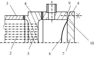
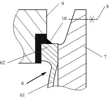
[0032] One of the specific implementations of the heat exchanger diaphragm sealing seam welding machine of the present application, the heat exchanger diaphragm sealing seam welding machine is applied to the welding of the heat exchanger diaphragm sealing seam 10, referring to the prior art figure 1 with figure 2 As shown, the heat exchanger includes a tube bundle 2, a tube shell 3 and a tube box 4, and the tube bundle 2 is pierced through the tube sheet 5, wherein: the tube box 4 is provided with a spherical diaphragm sealing disc 6, and the spherical diaphragm sealing disc 6 is arranged in the tube box Between the end 9 and the pipe box end cover 7; the spherical diaphragm sealing disc 6 includes a spherical membrane 61 arranged in the middle and a flat edge ring 62 arranged along the outer circumference of the spherical membrane 61; the flat edge ring 62 It is sealed with the pipe box end 9 through a sealing weld 10 ; the pipe box end 9 is fixedly connected with the pipe b...
Embodiment 2
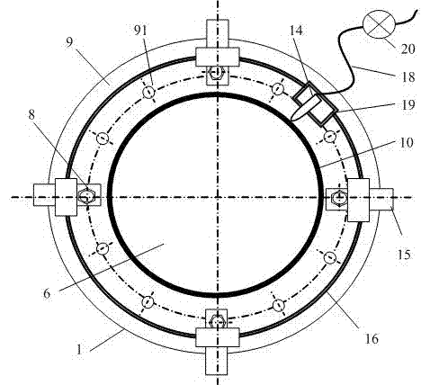
[0039] The second specific embodiment of the heat exchanger diaphragm sealing seam welding machine of the present application, the main technical solution of this embodiment is the same as that of embodiment 1, and the features not explained in this embodiment adopt the explanation in embodiment 1, No further details will be given here. The difference between this embodiment and embodiment 1 is that the reference image 3 As shown, the frame 12 is provided with an adjustment spoke 15 with a chute in the middle, and the frame 12 is fixed to the pipe box end 9 through the adjustment spoke 15 . Generally speaking, the 9 manholes at the end of the pipe box are relatively fixed and designed as 500mm to The variation range of 700mm, adjust the radial expansion and contraction of the spoke 15, which can be applied to the threaded hole 91 center circle of the pipe box end 9 600mm to The range of variation is 800mm, but the above range of variation can be changed according to d...
Embodiment 3
[0042] The third specific embodiment of the heat exchanger diaphragm sealing seam welding machine of the present application, the main technical solution of this embodiment is the same as that of embodiment 1, and the features not explained in this embodiment adopt the explanation in embodiment 1, No further details will be given here. The difference between this embodiment and Embodiment 1 is that the installation of the frame 12 and the pipe box 4 does not need to use the threaded hole 91 at the end 9 of the pipe box. Instead refer to Figure 5 As shown, the frame 12 is fastened to the pipe box outer circle 1 of the pipe box end 9 by tightening bolts 21 . If necessary, depending on the situation of the threaded holes 91, the number of tightening bolts 21 can be appropriately increased to enhance the connection rigidity.
PUM
 Abstract
Description
Claims
Application Information
 - Generate Ideas
- Intellectual Property
- Life Sciences
- Materials
- Tech Scout
- Unparalleled Data Quality
- Higher Quality Content
- 60% Fewer Hallucinations
Browse by: Latest US Patents, China's latest patents, Technical Efficacy Thesaurus, Application Domain, Technology Topic, Popular Technical Reports.
© 2025 PatSnap. All rights reserved.Legal|Privacy policy|Modern Slavery Act Transparency Statement|Sitemap|About US| Contact US: help@patsnap.com