A power switch tube isolated gate drive circuit for a power converter

A power switch tube and power converter technology, which is applied in the direction of output power conversion devices, electrical components, high-efficiency power electronic conversion, etc., can solve problems such as grid breakdown of power tubes, control failure, and power switch tube malfunctions. , to achieve the effect of preventing false opening, improving reliability and reducing driving loss

Inactive Publication Date: 2016-03-30
SOUTHEAST UNIV
View PDF3 Cites 15 Cited by
  • Summary
  • Abstract
  • Description
  • Claims
  • Application Information

AI Technical Summary

Problems solved by technology

However, this magnetic isolation drive circuit also has obvious disadvantages. Due to the influence of the winding process, the isolation drive transformer T will produce a certain leakage inductance, and the leakage inductance will resonate with the DC blocking capacitor at the moment of turning on and off, eventually causing A certain voltage spike is superimposed on the output level of the drive circuit, and the voltage spike may cause a malfunction of the power switch tube and cause the control to fail
Not only that, the excessive resonance voltage spike caused by the leakage inductance will also cause the gate of the power tube to be broken down. For the wide bandgap device that is easier to be broken down, it is especially necessary to have a negative voltage on the gate when the device is turned off.

Method used


Image

  • A power switch tube isolated gate drive circuit for a power converter
  • A power switch tube isolated gate drive circuit for a power converter
  • A power switch tube isolated gate drive circuit for a power converter

Examples


Embodiment Construction

[0017] The technology of the present invention will be described in detail below in conjunction with the accompanying drawings.

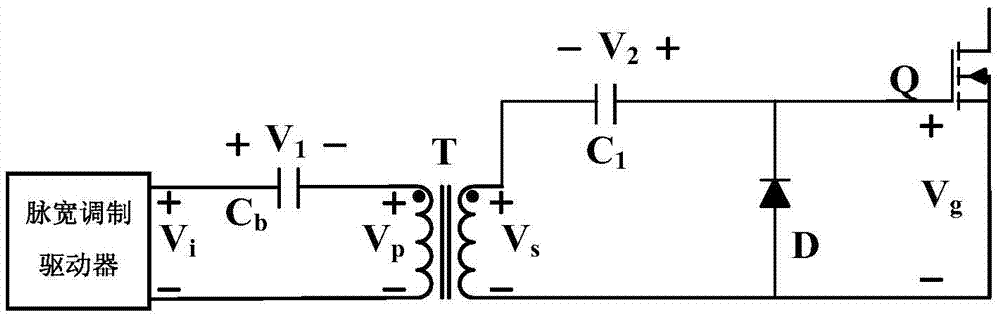
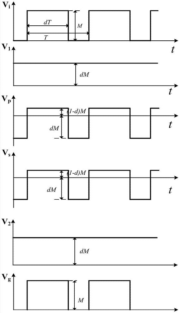
[0018] see image 3 , the present invention includes the prior art figure 1 The same pulse width modulation driver that generates the control signal, the isolation drive transformer T, and the primary side DC blocking capacitor C b , Secondary side DC blocking capacitor C 1 , diode D and driven switching tube Q, the voltage direction on each component is as follows figure 1 , 3 shown. The output positive terminal of the pulse width modulation driver passes through the DC blocking capacitor C b Connect the terminal with the same name on the primary side of the isolation transformer T, connect the non-identical terminal on the primary side of the isolation transformer T to the output negative terminal of the PWM driver, and connect the terminal with the same name on the secondary side of the isolation transformer T to the DC blocking capacitor C ...


PUM


Abstract

A power switch tube isolated gate drive circuit for a power converter comprises a pulse width modulation driver, an isolation driving transformer T, a blocking capacitor Cb, a capacitor C1, a diode D and a driven switch tube Q which constitute an isolated gate drive circuit in the prior art. According to the invention, on the basis of the above circuit, a resistor R1 in parallel with the capacitor C1 is additionally installed; a capacitor C2 is additionally installed to be in parallel connection with a resistor R2 and connected to a cathode of the diode D; after the capacitor C2 and the resistor R2 are in parallel connection, the other end of the capacitor C2 is connected between the capacitor C1 and a grid electrode of the driven switch tube Q. The capacitor C2, the resistor R2 and the diode D form a negative voltage source to provide a stable negative voltage in turn-off of the switch tube Q. Accidental switch-on of the switch tube in the switch-off process because of various crosstalks is prevented, and the reliability of the system is raised.

Description

technical field [0001] The invention relates to a power converter in the switch circuit technology, in particular to a power switch tube isolation barrier driving circuit of the power converter. Background technique [0002] Modern electronic equipment puts forward requirements on lightness and high efficiency for its power supply device (power converter), which makes the power density and switching frequency of the power converter continue to increase, the bridge topology with larger power capacity, and the new type of power converter with better performance Devices such as insulated gate field effect transistors (IGBTs) are widely used. Due to material limitations, traditional silicon-based power devices have approached or even reached the intrinsic limit of their materials in many aspects, and wide bandgap devices such as silicon carbide (SiC) and gallium nitride (GaN) have emerged. All of these put forward higher requirements such as faster, more efficient, and more rel...

Claims


Application Information

Patent Timeline
Patent Type & Authority Applications(China)
IPC IPC(8): H02M1/08
CPCH02M1/08H02M1/0054Y02B70/10
Inventor 孙伟锋朱俊杰俞居正钱钦松卜爱国陆生礼时龙兴
Owner SOUTHEAST UNIV
Why Eureka
Try Eureka