
Direct-air-cooling power generation system with natural ventilation cooling tower

A technology of natural ventilation and cooling towers, applied in the direction of water shower coolers, direct contact heat exchangers, engine components, etc. Sensitivity to hot air backflow and other issues, to achieve the effects of reducing fan power consumption, reducing film condensation, and improving stability and reliability

Inactive Publication Date: 2016-04-06
WUHAN KAIDI ELECTRIC POWER ENG
View PDF7 Cites 6 Cited by
  • Summary
  • Abstract
  • Description
  • Claims
  • Application Information

AI Technical Summary

Problems solved by technology

The direct air-cooling system has the advantages of simple system and good heat exchange effect, but the general direct air-cooling system adopts fan forced ventilation cooling, not only the fan noise is large, the fan consumes power, and the layout of the mechanical ventilation direct air-cooling system is affected by the dominant wind direction in summer Restricted, and sensitive to strong wind and hot air backflow, affecting the stable and safe operation of the turbogenerator
[0004] Moreover, the louvers of the external louvers of natural ventilation cooling towers are arranged vertically at present. When a certain louver is closed, the ventilation space of a part of the heat exchange tubes is completely closed, resulting in the isolation of these heat exchange components and stopping the operation, which affects the heat exchange. Efficiency of Thermal Components

Method used


Image

  • Direct-air-cooling power generation system with natural ventilation cooling tower
  • Direct-air-cooling power generation system with natural ventilation cooling tower
  • Direct-air-cooling power generation system with natural ventilation cooling tower

Examples


Embodiment Construction

[0020] In order to make the object, technical solution and advantages of the present invention clearer, the present invention will be further described in detail below in conjunction with the accompanying drawings and embodiments. It should be understood that the specific embodiments described here are only used to explain the present invention, not to limit the present invention.

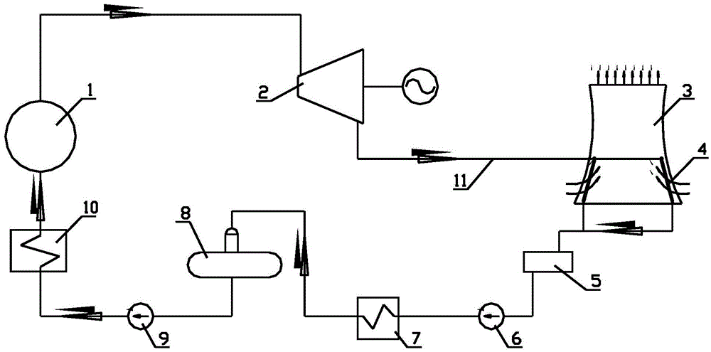
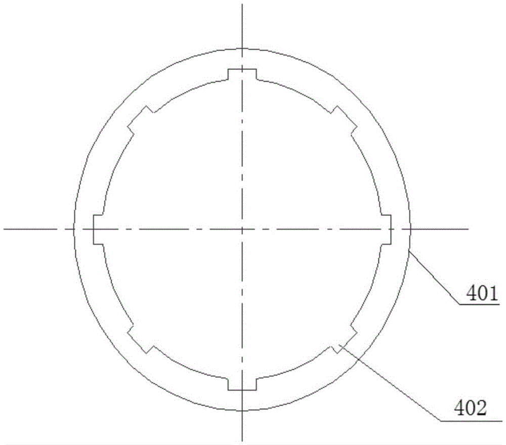
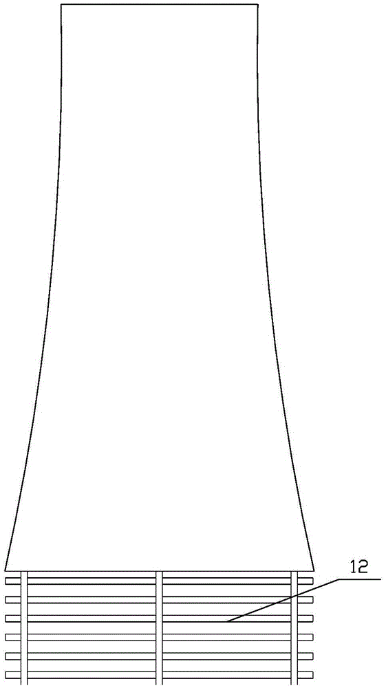
[0021] In a preferred embodiment of the present invention, as Figure 1-Figure 3 As shown, a direct air-cooled power generation system using a natural draft cooling tower, the system includes a boiler 1, a turbogenerator set 2, an air-cooled condenser 4, a condensate tank 5, a condensate pump 6, a low-pressure heater 7, and a deaerator 8. Feed water pump 9, high-pressure heater 10, and related connecting pipelines. The system also includes a natural draft cooling tower 3. The bottom of the natural draft cooling tower 3 is evenly opened with multiple air inlets along the circumference. The natural d...


PUM


Abstract

The invention discloses a direct-air-cooling power generation system with a natural ventilation cooling tower. The direct-air-cooling power generation system comprises a boiler, an air-cooling condenser and the natural ventilation cooling tower. A plurality of air inlets are evenly formed in the bottom of the natural ventilation cooling tower in the circumferential direction. An air outlet is formed in the top of the natural ventilation cooling tower. The air-cooling condenser comprises a heat exchange pipe bundle which is composed of multiple heat exchange pipes. The heat exchange pipe bundle is arranged on the inner sides or the outer sides of the air inlets. Threads or grooves are formed in the inner surfaces of the heat exchange pipes. Fins are arranged on the outer sides of the heat exchange pipes. Multiple sets of shutters are arranged on the portion, on the peripheries of the air inlets, of the natural ventilation cooling tower. Each set of shutters include a plurality of blades which are horizontally arranged. By means of the direct-air-cooling power generation system, the power consumption of the direct-air-cooling power generation system can be lowered, the influences of natural air on running of the air-cooling system and a power generation set are reduced as much as possible, and the direct-air-cooling power generation system has important significance in improving operating economy, stability and reliability of a power plant.

Description

technical field [0001] The invention specifically relates to a direct air-cooled power generation system using a natural draft cooling tower. Background technique [0002] Generally speaking, the construction of thermal power plants must have two major conditions: fuel and water. In my country's Northwest and North China, coal resources are abundant, but water resources are poor, and water has become a "bottleneck" problem for the development of thermal power plants in this area. The cooling medium of air-cooling technology is air. Compared with wet-cooling units of the same capacity, the biggest advantage of air-cooling units is that they can save water significantly. Therefore, air-cooling technology power generation systems have great advantages in water-scarce areas. [0003] Air-cooled power generation is further divided into direct air-cooled power generation and indirect air-cooled power generation. The direct air-cooling system has the advantages of simple system a...

Claims


Application Information

Patent Timeline
Patent Type & Authority Applications(China)
IPC IPC(8): F01K11/02F01D25/12F28C1/00F28B1/06
CPCF01K11/02F01D25/12F28B1/06F28C1/00
Inventor 邓涛马宝社王金龙邓宏杰赵志华
Owner WUHAN KAIDI ELECTRIC POWER ENG
Learn More