Intelligent agriculture monitoring system device

A monitoring system and agricultural technology, applied in general control systems, control/regulation systems, program control, etc., can solve the problems of complicated cables, high costs, and inability to understand the conditions of greenhouses at the first time

Inactive Publication Date: 2016-04-06
HEILONGJIANG UNIVERSITY OF SCIENCE AND TECHNOLOGY
View PDF6 Cites 4 Cited by
  • Summary
  • Abstract
  • Description
  • Claims
  • Application Information

AI Technical Summary

Problems solved by technology

[0003] The purpose of the present invention is to provide an intelligent agricultural monitoring system device in order to overcome the complexity, high cost and control deficiencies of cable layout in the existing vegetable greenhouse monitoring system, so that the staff cannot understand the situation of the greenhouse at the first time. Timely Judgment Issues

Method used


Image

  • Intelligent agriculture monitoring system device
  • Intelligent agriculture monitoring system device
  • Intelligent agriculture monitoring system device

Examples


Embodiment 1

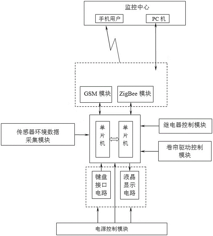
[0039] combine figure 1 Explain, a kind of intelligent agricultural monitoring system device, its composition comprises: single-chip microcomputer, rolling shutter, display screen, keyboard, two described single-chip microcomputers form single-chip processing module, between two described single-chip microcomputers, connect through serial mode, The single-chip processing module receives the signal of the sensor environment data acquisition module, the single-chip processing module also receives the signal of the relay control module, and the single-chip processing module also receives the signal of the rolling shutter drive control module, and the single-chip processing module The module also receives the signal of the power control module, and the single-chip processing module also receives the signal of the keyboard interface circuit, and the single-chip processing module transmits the signal to the liquid crystal display circuit, and the single-chip processing module and th...

Embodiment 2

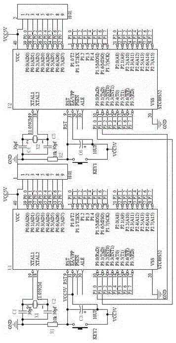
[0041] combine figure 2 Illustrate, the intelligent agricultural monitoring system device described in embodiment 1, the connection between two described single-chip microcomputers comprises single-chip microcomputer U1 and single-chip microcomputer U2, and No. 19 pins of described single-chip microcomputer U1 are connected in parallel with one end of crystal oscillator X1 and capacitor C1. One end, the No. 18 pin of the single-chip microcomputer U1 is connected in parallel with the other end of the crystal oscillator X1 and one end of the capacitor C2, and the other end of the capacitor C1 is connected in parallel with the other end of the capacitor C2 and one end of the resistor R1, and the The other end of the resistor R1 is connected in parallel with one end of the switch KEY2, one end of the capacitor C3, the No. 9 pin of the single-chip microcomputer U1 and the No. 31 pin of the single-chip microcomputer U1, and the No. 31 pin of the single-chip microcomputer U1 is conne...

Embodiment 3

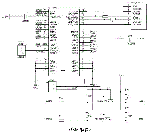
[0044] combine image 3 Description, the intelligent agricultural monitoring system device described in Embodiment 1, the short-distance wireless communication technology module includes chip IC1, the No. 10 pin of the chip IC1 is grounded through the capacitor C18, and the No. 39 pin of the chip IC1 One end of the capacitor C12, one end of the capacitor C11, one end of the inductor L2, the No. 39 pin of the chip IC1, one end of the resistor R2 and one end of the resistor R3 are connected in parallel with the pins, and the other end of the capacitor C12 is grounded. The other end of the capacitor C11 is grounded, the other end of the resistor R2 is grounded through the light-emitting diode D11, the other end of the resistor R3 is grounded through the light-emitting diode D12, and the other end of the inductor L2 is connected in parallel with one end of the capacitor C13 , the No. 21 pin of the chip IC1, one end of the capacitor C14, the No. 24 pin of the chip IC1, one end of t...


PUM


Abstract

The invention relates to an intelligent agriculture monitoring system device. A single-chip microcomputer processing module can be formed by two single-chip microcomputers, which are serially connected together. The single-chip microcomputer processing module can be used to receive signals of a sensor environment data acquisition module, a relay control module, a roller shutter driving control module, a power supply control module, and a keyboard interface circuit. The single-chip microcomputer processing module can be used to transmit the signals to a liquid crystal display circuit. The bidirectional signal transmission between the single-chip microcomputer processing module and a global mobile communication module, a short-distance wireless communication technology module can be realized. The global mobile communication module and the short-distance wireless communication technology module are cooperated with a cell phone, and are also cooperated with a host computer. The intelligent agriculture monitoring system device is used for the agriculture monitoring.

Description

technical field [0001] The invention relates to an intelligent agricultural monitoring system device. Background technique [0002] In agricultural production, the temperature and humidity in the greenhouse are monitored manually by time-sharing and sub-regional sampling. Due to the relatively large area of ​​the greenhouse, the workload is heavy, the reliability is poor, the detection targets are scattered, and there are many measurement points. Moreover, the existing monitoring system for vegetable greenhouses has complex cable layout, high cost and insufficient control, making it difficult to repair the lines once a problem occurs, wasting resources and occupying a large space. At the same time, depending on the cable for information transmission, there will be problems such as easy interference and low data transmission efficiency, which makes it impossible for the staff to understand the situation of the greenhouse in the first place, so as to take timely countermeasur...

Claims


Application Information

Patent Timeline
Patent Type & Authority Applications(China)
IPC IPC(8): G05B19/042
CPCG05B19/0428G05B2219/24024
Inventor 史健婷王建才季晓丽李志军
Owner HEILONGJIANG UNIVERSITY OF SCIENCE AND TECHNOLOGY
Why Eureka
Try Eureka