Novel power-on surge current suppression circuit

A surge current and suppressing circuit technology, applied in the field of AC-DC switching power supply, can solve the problems of reducing the reliability of AC-DC converters, large power consumption of NTC resistors, and large pull-in current of relays, so as to achieve no need for debugging and starting The effect of fast speed and simple circuit

Inactive Publication Date: 2016-04-06
GUANGDONG UNIV OF TECH
View PDF4 Cites 16 Cited by
  • Summary
  • Abstract
  • Description
  • Claims
  • Application Information

AI Technical Summary

Problems solved by technology

For example, the cost of connecting NTC thermistors in series is the lowest, but the AC input current always flows through the thermistors during normal operation, resulting in high power consumption of NTC resistors, high temperature and high current for a long time, and more seriously, power failure Finally, you must wait for the NTC resistor to cool down to normal temperature before powering on, otherwise the thermistor will lose its ability to suppress the surge current and reduce the reliability of the AC-DC converter; the AC zero-crossing trigger method requires a thyristor rectifier , and also need to add auxiliary power supply, AC zero-crossing detection circuit, high cost and complicated circuit; although the parallel connection of power resistor and electromagnetic relay can better solve the problem of the startup surge current and the power consumption of the current-limiting resistor during the normal operation of the converter The contradiction, but the relay pulls in a large current, the mechanical contact reliability is poor, and the volume is large

Method used


Image

  • Novel power-on surge current suppression circuit
  • Novel power-on surge current suppression circuit
  • Novel power-on surge current suppression circuit

Examples


Embodiment 1

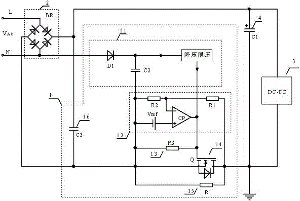
[0032] A new type of power-on surge current suppression circuit, such as figure 1 As shown, it includes a power supply circuit 11, a surge current suppression resistor terminal voltage sampling and comparison circuit 12, a discharge resistor 13, a low on-resistance N-channel power MOS tube 14, a surge current suppression resistor 15 and an optional small capacity high frequency filter capacitor 16, wherein the inrush current limiting resistor 15 can be a non-inductive universal power resistor or an NTC thermistor. figure 1 Among them, the L terminal and N terminal of the AC input line are connected to the rectifier bridge 2 and also include a DC-DC converter 3 , and the power-on surge current suppression circuit is connected between the rectifier bridge 2 and the DC-DC converter 3 .

[0033] The power supply circuit 11 includes a rectifier diode D1, an energy storage filter capacitor C2 and a step-down voltage limiting circuit. The step-down voltage limiting circuit can be a p...

Embodiment 2

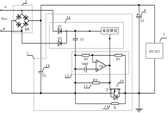
[0041] Such as figure 2 As shown, the difference between this embodiment and Embodiment 1 is that the power supply circuit 11 is provided with two rectifier diodes. In the figure, the rectifier diode D1 is connected to the L terminal of the AC input line, and the rectifier diode D2 is connected to the end of the AC input line. The N terminal constitutes a full-wave rectification, which can reduce the capacity of the energy storage filter capacitor C2.

Embodiment 3

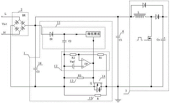
[0043] Such as image 3 As shown, compared with Embodiment 1 and Embodiment 2, the difference of this embodiment is that the power-on surge current suppression circuit is applied to the APFC converter of the Boost topology. In the figure, the anode of the rectifier diode D1 is connected to the positive end of the rectifier bridge 2. In this case, the rectifier diode D1 only plays an isolation role to prevent the energy storage filter capacitor C2 from discharging through the DC-DC converter. In other embodiments, the anode of the rectifier diode D1 may also be connected to the N terminal or the L terminal of the AC input line.


PUM


Abstract

The invention relates to a novel power-on surge current suppression circuit. The novel power-on surge current suppression circuit comprises a power supply circuit, a surge current suppression resistor end voltage sampling and comparison circuit, a relief resistor, a metal oxide semiconductor (MOS) transistor, a surge current suppression resistor and an optional small-capacity high-frequency filtering capacitor, wherein the power supply circuit comprises a rectification diode, an energy storage filtering capacitor and a buck voltage limitation circuit, the surge current suppression resistor end voltage sampling and comparison circuit comprises a first end voltage sampling resistor, a second end voltage sampling resistor, a reference voltage source and a comparator, a drain of the MOS transistor is connected with a DC-DC converter, a source of the MOS transistor is connected with a negative end of a rectifier bridge, a grid of the MOS transistor is connected with an output end of the power supply circuit, an input end of the power supply circuit is connected with an AC N/L end, the surge current suppression resistor is connected in parallel to the drain and the source of the MOS transistor, the relief resistor is connected in parallel to the grid and the source of the MOS transistor, and the optional small-capacity high-frequency filtering capacitor is connected between a positive end and the negative end of the rectifier bridge. With the power-on surge current suppression circuit disclosed by the application, the power-on surge current is suppressed better, the power consumption of an MOS transistor driving circuit is low, the starting speed is fast, and the power-on time allowed again is short.

Description

technical field [0001] This application relates to an AC-DC switching power supply, and specifically relates to a novel power-on surge current suppression circuit, which is generally applicable to AC-DC converters with various topological structures such as flyback, forward or APFC. Background technique [0002] In the AC-DC drive circuit, after the alternating current is rectified, it is directly or indirectly filtered by a large capacitor. The terminal voltage of the filter capacitor rises from zero at the moment of power-on. If it is just near the maximum value of the sinusoidal alternating current when the power is turned on, there will be a transient high current of up to hundreds of amperes at the moment of power-on, which will affect the power grid and the AC-DC converter connected in series. Devices in the input channel, such as fuses, power frequency rectifier diodes, and filter capacitors, have caused severe high-current shocks. The size and duration of the tran...

Claims


Application Information

Patent Timeline
Patent Type & Authority Applications(China)
IPC IPC(8): H02M1/32H02H9/02
CPCH02H9/02H02H9/025H02M1/32
Inventor 潘永雄郑明治陈林海黄明旭徐思蔚
Owner GUANGDONG UNIV OF TECH
Why Eureka
Try Eureka