Pipe cavity bracket

A lumen and tube body technology, which is applied to stents, blood vessels, and devices of human tubular structures, can solve problems such as rupture and failure of intracavitary isolation therapy, and achieve the effect of avoiding wrinkles and blood obstruction

Active Publication Date: 2016-04-20
LIFETECH SCIENTIFIC (SHENZHEN) CO LTD
View PDF6 Cites 40 Cited by
  • Summary
  • Abstract
  • Description
  • Claims
  • Application Information

AI Technical Summary

Problems solved by technology

If the blood flow continues to flow in, it may cause the false lumen of the dissection or the cavity of the aneurysm to contin

Method used


Image

  • Pipe cavity bracket
  • Pipe cavity bracket
  • Pipe cavity bracket

Examples


no. 1 example

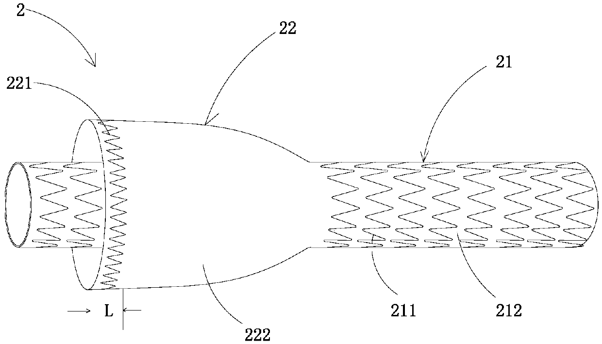
[0055] see image 3 According to the first embodiment of the present invention, the lumen stent 2 includes a first tubular body 21 and a second tubular body 22. The second tubular body 22 is sheathed outside the first tubular body 21 and covers at least the first tubular body 21. In one part, one end of the second pipe body 22 is sealingly connected with the outer peripheral surface of the first pipe body 21 .

[0056] Specifically, the first tubular body 21 has the ability to expand radially, can be compressed under the action of an external force, and can self-expand after the external force is removed or return to the original shape by mechanical expansion (such as balloon expansion) and maintain the original shape, In this way, after being implanted into the lumen, it can be fixed in the lumen by close contact with the wall of the lumen through its radial support force. The first tube body 21 includes a first radial support structure 211 provided on the entire tube body. ...

no. 2 example

[0091] see Figure 12 , the difference from the endoluminal stent of the first embodiment is that, according to the second embodiment of the endoluminal stent 2, the nozzle of the second tubular body 22 close to the proximal end 23 is sealingly connected with the outer peripheral surface of the first tubular body 21, forming The nozzle is closed, and the nozzle near the distal end 24 of the second tube body 22 is open. The above-mentioned second tube body 22 is located near the proximal end 23 of the first tube body 21, but those skilled in the art should know that the illustration is only used as an example, and is not a limitation of the present invention. Those skilled in the art can base on According to the teaching of the present invention, the second tube body 22 is arranged near the distal end 24 of the first tube body 21 .

[0092] see Figure 13A and 13B Specifically, the second pipe body 22 may further include a straight pipe section 221a, a tapered pipe section 2...

no. 3 example

[0095] see Figure 14 , the difference from the endoluminal stent of the second embodiment is that, according to the third embodiment, the two nozzles of the second tube body 22 of the endoluminal stent 2 are in sealing connection with the outer peripheral surface of the first tube body 21, forming Two closed orifices. At this time, if both nozzles of the second tube body 22 are sealed, similar to the second embodiment, the channel or opening forming the type I endoleak can also be cut off after implantation. During the sealing process, there is also no need to add other sealing or filling materials in the lumen 12 stent 2 or after implantation, only the blood flowing in in the normal blood circulation can realize the sealing without additional sealing or filling Biological risks posed by materials.


PUM

PropertyMeasurementUnit
Widthaaaaaaaaaa
Diameteraaaaaaaaaa
Wire diameteraaaaaaaaaa

Abstract

The invention discloses a pipe cavity bracket. The pipe cavity bracket comprises a first pipe body and a second pipe body which sleeves the first pipe body, wherein at least one end of the second pipe body is in sealed connection with the outer surface of the first pipe body; in a radial supporting section of the pipe cavity bracket, the first pipe body comprises at least one first radial supporting structure which is arrayed along the peripheral direction of the first pipe body; the second pipe body comprises at least one second radial supporting structure which is arrayed along the peripheral direction of the second pipe body and a covering membrane covering the second radial supporting structure; a radial deformation capability of the second radial supporting structure is greater than that of the first radial supporting structure. After the pipe cavity bracket is planted, a semi-sealed gap can be formed between the first pipe body and the second pipe body or between the second pipe body and a pipe cavity wall; blood flowing into the gap can be used as a filling material to block an I type inner leakage channel, so that the blood is prevented from flowing into tumors or an interlayer. Under the impact of the blood, the first pipe body and the second pipe body both can keep a radial supporting shape and the end faces of near ends of the first pipe body and the second pipe body are not deformed, so that the blood flowing into the pipe cavity is prevented from being blocked.

Description

technical field [0001] The invention relates to an implanted medical device, in particular to a lumen support and a lumen support system. Background technique [0002] At present, a lumen stent can be used to implement endovascular isolation to isolate a lesion area in a human lumen, for example, a lumen stent can be used to isolate an arterial dissection or aneurysm in a blood vessel. This method has the advantages of less surgical trauma, less intraoperative blood transfusion, faster postoperative recovery and shorter hospital stay, so it has gradually replaced traditional open surgery. The luminal stent usually has the ability to expand radially, and is fixed in the lumen by using its radial support force to cling to the lumen wall of the vessel. In order to prevent the stent from falling off, the stent must have a sufficiently large radial support force, and the greater the radial support force, the stronger the rigidity of the stent after radial deployment. However, d...

Claims


Application Information

Patent Timeline
IPC IPC(8): A61F2/07
CPCA61F2/07A61F2210/0076A61F2/848A61F2002/061A61F2002/077A61F2002/8486A61F2220/0025A61F2220/005A61F2220/0058A61F2220/0075A61F2230/0067A61F2250/0003A61F2250/0018A61F2250/0039A61F2250/0063A61F2250/0069A61F2/852A61F2/86A61F2/94
Inventor 肖本好
Owner LIFETECH SCIENTIFIC (SHENZHEN) CO LTD
Why Eureka
Try Eureka