

Automatic control SCR flue gas denitrification urea pyrolysis system
A flue gas heating and urea technology, which is applied in the field of energy saving and emission reduction in power plants, can solve the problems of high energy consumption and high operating costs of the urea pyrolysis system, and achieve the effects of reducing evaporation in the tower, increasing residence time, and saving water consumption
- Summary
- Abstract
- Description
- Claims
- Application Information
AI Technical Summary
Problems solved by technology
Method used
Image

Examples
Embodiment Construction
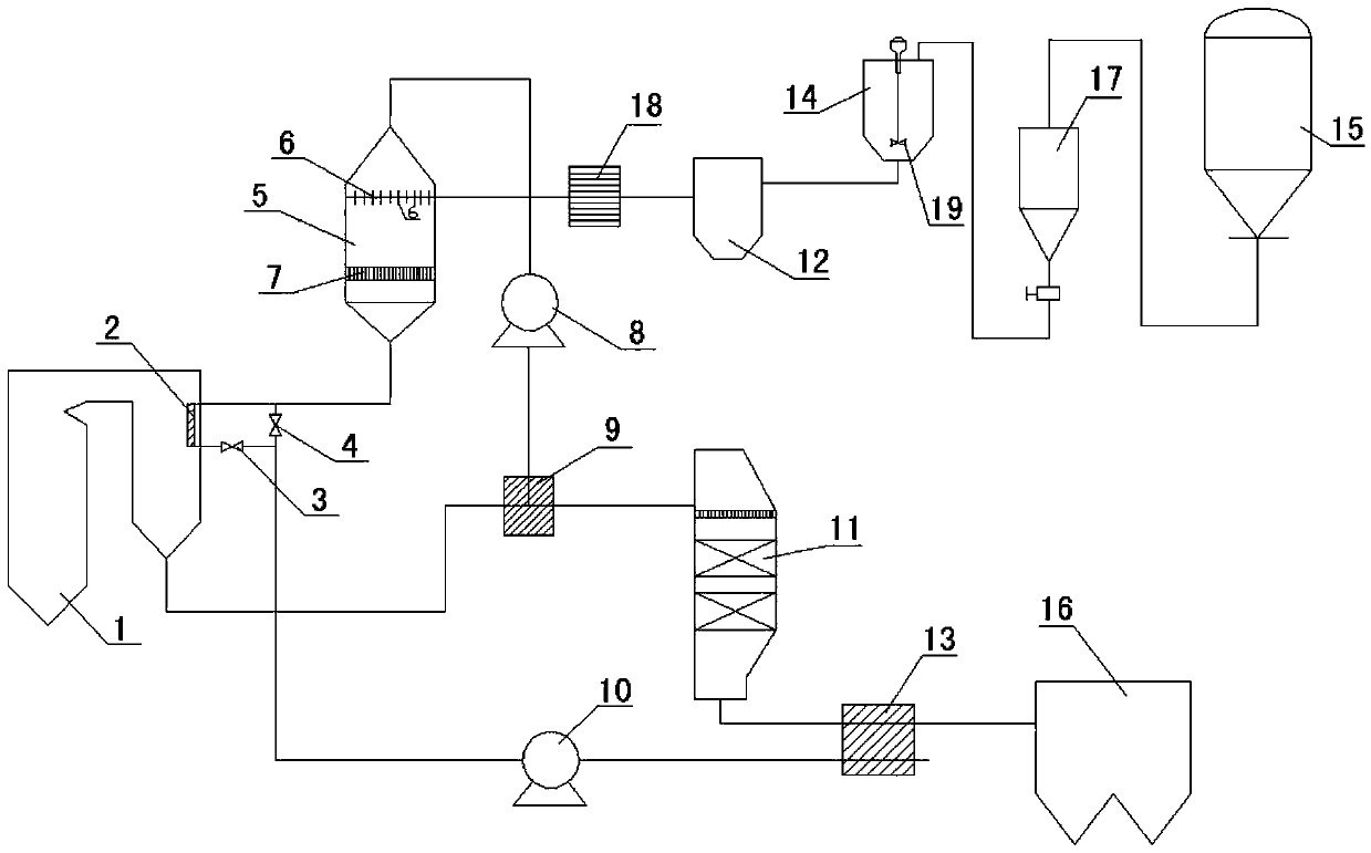
[0022] see figure 1 , the structural form of the automatic control SCR flue gas denitrification urea pyrolysis system in this embodiment is:
[0023] An air-gas heat exchanger 13 is arranged in the inlet flue of the electrostatic precipitator 16 to form an air heating unit, and a group of flue gas heating tube bundles 2 are arranged in the boiler 1 to form an air reheating unit, and air is introduced into the air-gas heat exchange through the induced draft pump 10 13, and is heated in the gas-gas heat exchanger 13, and after being reheated by the flue gas heating tube bundle 2, the heat source temperature required for urea pyrolysis is reached to become high-temperature air, and the high-temperature air is sent into the urea pyrolysis furnace 5 and sprayed The atomized urea solution is mixed and pyrolyzed to generate ammonia / air mixed gas. The ammonia / air mixed gas is sprayed into the inlet flue of SCR denitrification reactor 11 through the booster pump 8 and then through the ...
PUM
 Abstract
Description
Claims
Application Information