Two-stage-parallel cycloidal steel ball speed reducer

A technology of cycloidal steel balls and reducers, which is applied to transmission parts, friction transmission devices, belts/chains/gears, etc., can solve the problems of large load on the arm bearing, small transmission ratio, and large inertial force, etc. Transmission accuracy, high transmission accuracy, and the effect of reducing load

Inactive Publication Date: 2016-04-20
JIANGSU TAILONG MACHINERY GRP CO CO LTD
View PDF8 Cites 12 Cited by
  • Summary
  • Abstract
  • Description
  • Claims
  • Application Information

AI Technical Summary

Problems solved by technology

Among them, the single-stage K-H-V type transmission with small tooth difference can realize relatively small transmission, especially the single-stage cycloidal steel ball transmission, because it adopts the combination of the number of teeth with two tooth differences, the realizable transmission ratio is even smaller, and it is difficult to adapt to robot equipment. The need for low-speed operation
The two-stage NN type transmission with small tooth difference can achieve a higher transmission ratio, but the common NN type cycloid steel ball transmission, the two planetary gears are installed on the same eccentric shaft section, the inertia force is large during transmission operation, and the load on the rotating arm

Method used


Image

  • Two-stage-parallel cycloidal steel ball speed reducer
  • Two-stage-parallel cycloidal steel ball speed reducer
  • Two-stage-parallel cycloidal steel ball speed reducer

Examples


Embodiment Construction

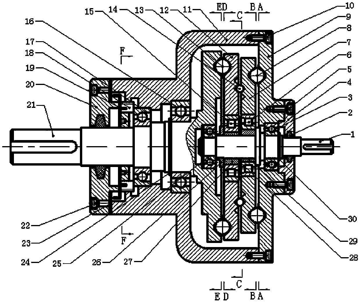
[0031] The accompanying drawing discloses the specific structure of an embodiment of the present invention without limitation, and the present invention will be further described below in conjunction with the accompanying drawings.

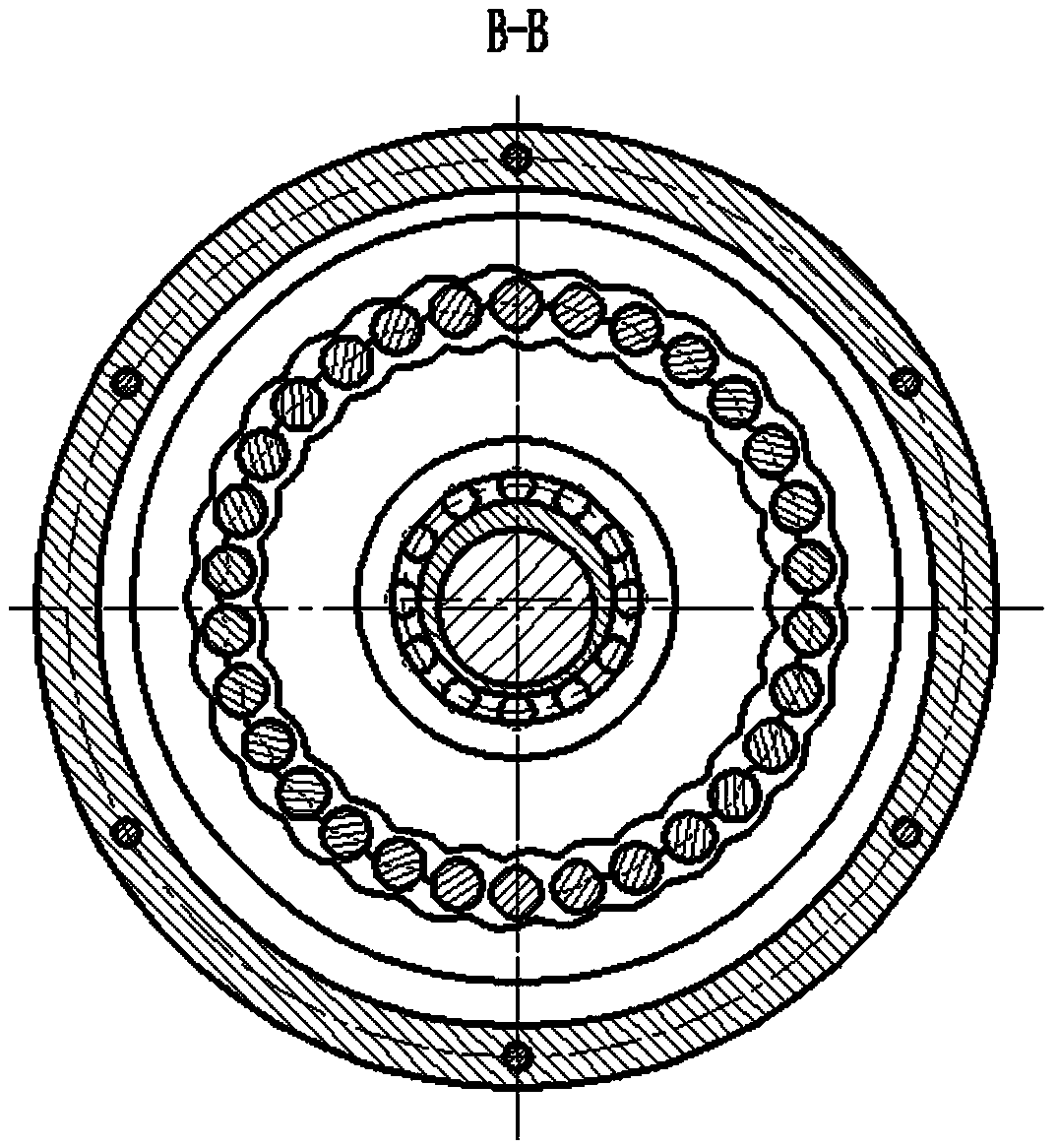
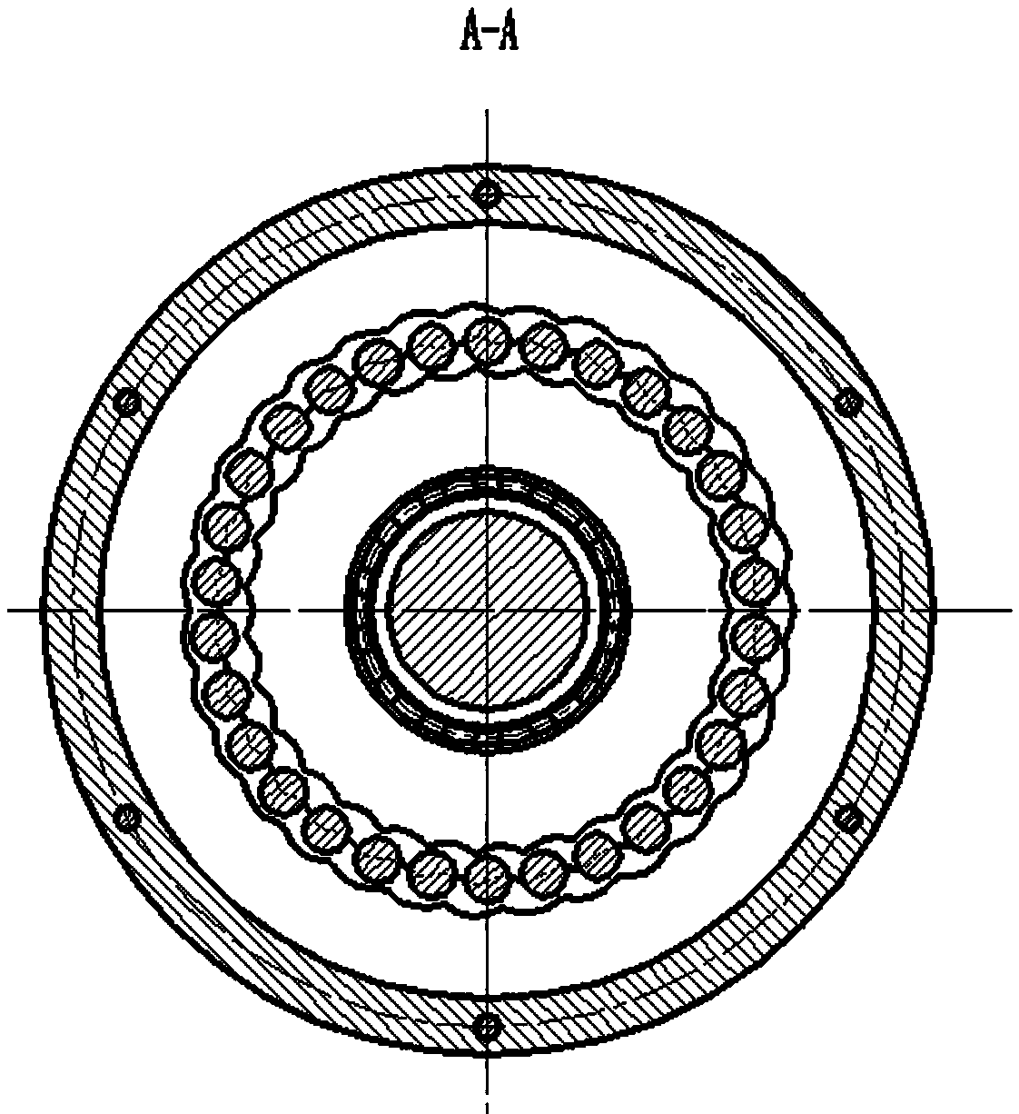
[0032] Figure 1 to Figure 6 A two-stage parallel cycloidal ball reducer is shown. The power is input by the input shaft (1). Since the input shaft (1) is fixedly connected with the eccentric sleeve I (29) through interference fit, the input shaft (1) drives the eccentric sleeve I (29) to rotate together, and passes through the eccentric sleeve I (29). The rotating arm bearing I (6) on the top drives the planetary disc I (7) to move. At the same time, the epicycloid closed groove on the right end surface of the planetary disk I (7) pushes the steel ball group (8) to move, and the steel ball group (8) is constrained by the hypocycloid closed groove on the left end surface of the end cover (9) , push back the planetary disk I (7) to rotate at a lo...


PUM


Abstract

The invention provides a two-stage-parallel cycloidal steel ball speed reducer, belonging to the field of precise mechanical transmission. The two-stage-parallel cycloidal steel ball speed reducer comprises a shell, an input shaft, a planetary disk I, an eccentric sleeve I, a steel ball set, a planetary disk II, an eccentric sleeve II, a steel ball set, an end cover, an output shaft, a pretension nut, a support bearing and a bearing end cover. The speed reducer adopts the NN two-stage-parallel few-tooth-difference planetary transmission basic structure; by using the inner and outer cycloidal sealed grooves in the end surfaces of the end cover, planetary disk and output shaft as tooth profiles and using steel balls as a medium, meshing transmission is performed; and the four-point contact of the steel balls and cycloidal sealed grooves is utilized to eliminate the tooth space. The speed reducer has the advantages of simple structure, small size, high transmission ratio, zero tooth space, high transmission accuracy and low impact. Meanwhile, as distinguished from the common NN cycloidal steel ball transmission, the two planetary disks are installed on different eccentric shaft sections in a 180-degree symmetric mode, and connected through a steel ball ring groove constant speed unit, thereby achieving the balance between meshing force and inertia force. The speed reducer has the advantages of small inertia force during transmission operation, low load of the swing arm bearing, and long service life.

Description

technical field [0001] The invention relates to a precision deceleration transmission device, which can be applied to precision mechanical transmission fields such as robots, numerical control machine tools, aviation, medical equipment, instruments and meters. Background technique [0002] In order to improve the transmission accuracy and control accuracy of precision machinery such as robots, the reduction transmission device is required to have the characteristics of compact structure, small size, large transmission ratio, small backlash, fast response, and high efficiency. At the same time, the reduction transmission device is required to have high Reciprocating positioning accuracy. [0003] The existing commonly used precision reduction transmission devices mostly adopt the mechanism form of single-stage K-H-V type or two-stage NN type transmission with small tooth difference. Among them, the single-stage K-H-V type transmission with small tooth difference can realize ...

Claims


Application Information

Patent Timeline
IPC IPC(8): F16H13/08F16H57/12F16H57/021
CPCF16H13/08F16H57/021F16H57/12F16H2057/125
Inventor 张鹏殷爱国孔霞张介禄
Owner JIANGSU TAILONG MACHINERY GRP CO CO LTD
Why Eureka
Try Eureka