Oil-gas mixed transportation pipeline device and method for simulating formation, blocking and melting of hydrates

A technology for hydrate generation and oil and gas mixed transportation. It is used in measurement devices, instruments, scientific instruments, etc., and can solve problems such as single hydrate, unsatisfactory plugging removal methods, and inability to consider the hydrate generation process.

Active Publication Date: 2016-04-20
CHINA UNIV OF PETROLEUM (EAST CHINA)
View PDF7 Cites 22 Cited by
  • Summary
  • Abstract
  • Description
  • Claims
  • Application Information

AI Technical Summary

Problems solved by technology

[0010] (1) The above patents can study the formation process of hydrate in the pipeline and the flow characteristics after hydrate formation, but cannot effectively analyze and study the clogging process and mechanism of hydrate in the pipeline
[0011] (2) The above patents are mainly used to study the prevention and generation process of hydrates in the pipeline, and cannot effectively study the decomposition processes of hydrates such as heating, depressurization, and injection after the formation of hydrates in the pipeline or after the pipeline is blocked.
[0012] (3) All the above patents can be used to study the blockage removal technology of hydrate in the pipeline, but the method used cannot consider the formation process of hydrate, and a single method is used for the blockage removal of hydrate
[0013] (4) The above patents are mainly used to study the plugging removal process of hydrates in the pipeline, and do not consider in detail the different states of hydrates after they are generated. The methods used are also uniform, which makes the effect of the plugging removal method not ideal
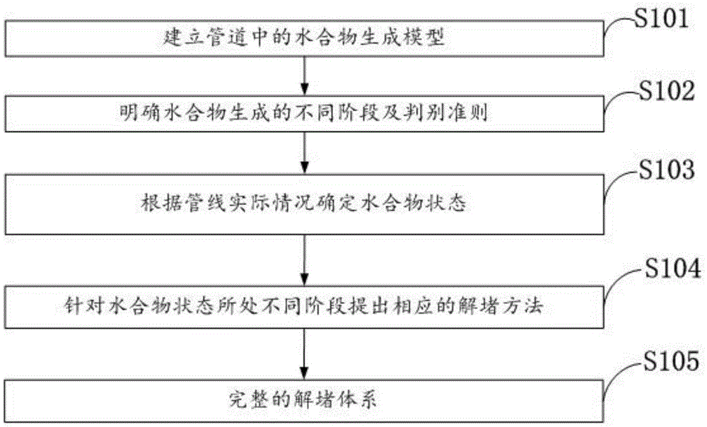
[0014] In short, the above patents are not comprehensive in the research on the entire process of hydrate formation, flow, blockage and decomposition in the pipeline. Therefore, the present invention designs an experimental device and a A comprehensive method capable of unblocking hydrate plugging according to its formation stage

Method used


Image

  • Oil-gas mixed transportation pipeline device and method for simulating formation, blocking and melting of hydrates
  • Oil-gas mixed transportation pipeline device and method for simulating formation, blocking and melting of hydrates

Examples


Embodiment Construction

[0054] In order to make the purpose and technical solution of the present invention clearer, the present invention will be further described in detail below with reference to the accompanying drawings.

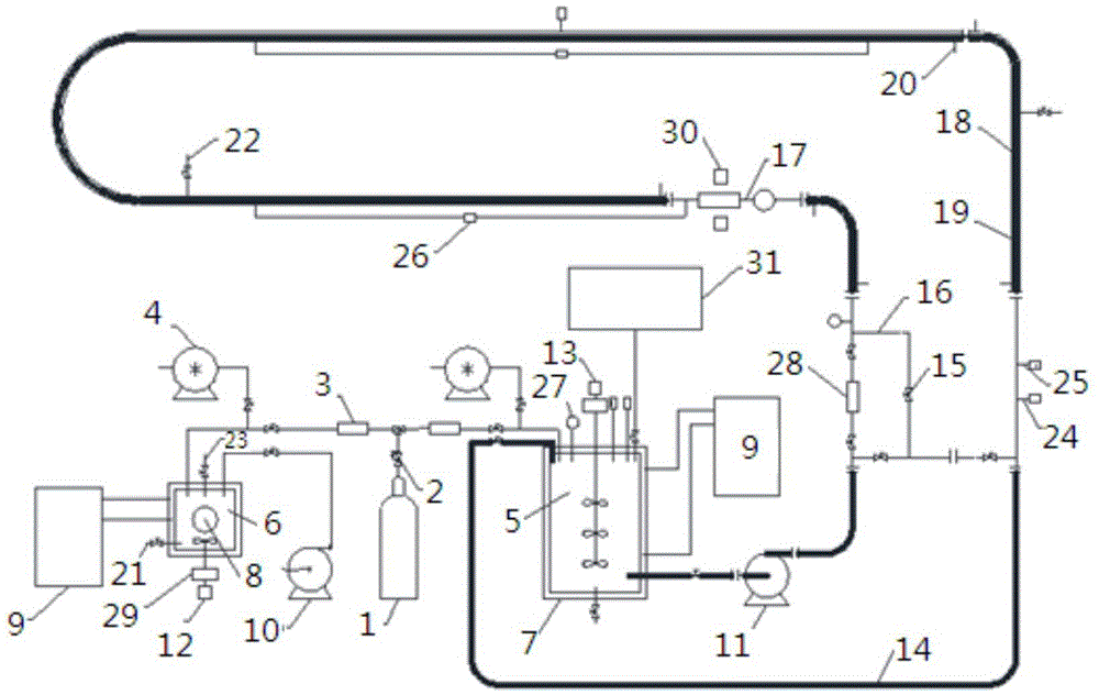
[0055] as attached figure 1 As shown, an oil and gas mixed transportation pipeline device includes a reactor system and a loop system, mainly composed of a gas supply system, a liquid injection system, a reaction system / circulation system, a temperature and pressure control system, a measurement system, and a data acquisition and processing system. six parts.

[0056] The temperature and pressure control system includes a cooling water circulator 9 , a loop liquid inlet / exhaust port 22 and a reaction kettle exhaust port 23 .

[0057] The measurement system includes a temperature sensor 24 , a pressure sensor 25 , a differential pressure sensor 26 , a pressure gauge 27 , a gas volume flow meter 3 , a mass flow meter 28 , a torque sensor 29 , a laser particle size analyzer 30 a...


PUM


Abstract

The invention discloses an oil-gas mixed transportation pipeline device and a method for simulating formation, blocking and melting of hydrates. The device comprises a reaction kettle I and a reaction kettle II, wherein the reaction kettle I and the reaction kettle II are connected with the same gas supplying system; a grouting port is formed in the reaction kettle I; the top of the reaction kettle II is communicated with the bottom of the reaction kettle II through a circulation pipeline, and a liquid injection port is formed in the circulation pipeline; each of the reaction kettle I and the reaction kettle II is provided with a temperature control device for adjusting the temperature; a detection device for detecting the reaction state of the natural gas hydrates in a pipeline is further mounted on the circulation pipeline and connected with a data processing system. The oil-gas mixed transportation pipeline device and the method for simulating formation, blocking and melting of the hydrates have a very good effect on controlling loss caused by long-time production suspension as a result of blocking of the pipeline in a high-risk blocking state.

Description

technical field [0001] The invention belongs to the technical field of pipeline safety control, and in particular relates to an oil-gas mixed transportation pipeline device and a simulation method for hydrate formation, blockage and ablation. Background technique [0002] Natural gas hydrate is a non-stoichiometric cage-like crystal substance formed by water and small molecular gases such as methane, ethane, carbon dioxide and hydrogen sulfide. During oil and gas extraction and transportation, due to high pressure and low temperature conditions, natural gas hydrates are easily formed to block pipelines and hinder normal production. Since the Soviet Union first discovered hydrate ice blockage in natural gas pipelines in 1934, with the continuous development of oil and gas resources to the deep water field, various problems caused by hydrates have gradually become a research hotspot in the field of oil industry flow security. Among them, the research on the prevention and con...

Claims


Application Information

Patent Timeline
Patent Type & Authority Applications(China)
IPC IPC(8): G01N33/00
CPCG01N33/00
Inventor 王武昌李玉星胡其会刘翠伟朱建鲁宋光春赵鹏飞姜凯叶晓
Owner CHINA UNIV OF PETROLEUM (EAST CHINA)
Why Eureka
Try Eureka