Microscopic polarization imaging device based on microwave sheet array and implement method thereof

A microwave sheet array, polarization imaging technology, applied in microscopes, optics, instruments, etc., can solve problems such as insufficient stability, low spatial resolution, and inability to measure the S3 component of the optically active component

Inactive Publication Date: 2016-04-20
FUZHOU UNIVERSITY
View PDF6 Cites 10 Cited by
  • Summary
  • Abstract
  • Description
  • Claims
  • Application Information

AI Technical Summary

Problems solved by technology

At present, the temporal and spatial resolution of framing and sub-aperture polarization imaging is high, but the optical path is complex, the stability is insufficient, and it is difficult to align images of different polarization states at the pixel level; Group modulation image polarization state, the existence of interference fringes leads to low spatial resolution; the split focal plane scheme can realize polarization state measurement through a single exposure, and the overall system is compact in structure and stable in performance. It has been used in the radar remote sensing of the US military System is the future development direction of polarization imaging technology
However, at present, the focal plane polarization imaging based on the micropolarizer array can only measure the first three components (S0, S1, S2) of the Stokes vector. The reason is that the S3 component representing the optical rotation component cannot be measured by simply changing the direction of the polarizer.

Method used


Image

  • Microscopic polarization imaging device based on microwave sheet array and implement method thereof
  • Microscopic polarization imaging device based on microwave sheet array and implement method thereof
  • Microscopic polarization imaging device based on microwave sheet array and implement method thereof

Examples


Embodiment Construction

[0038] The present invention will be further described below in conjunction with the accompanying drawings and embodiments.

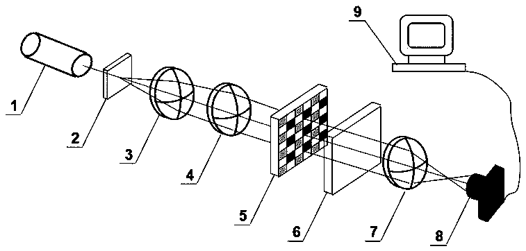
[0039] Please refer to figure 1 , the present embodiment provides a microscopic polarization imaging device based on a microwave plate array, which is characterized in that it includes a laser light source 1, a microscopic objective lens 3, a microscopic eyepiece 4, a microwave plate array 5, A unidirectional polarizer 6, an imaging lens 7 and a side array camera 8; the sample 2 to be measured is placed between the laser light source 1 and the microscopic objective lens 3 at the focal length position of the microscopic objective lens 3, and the present embodiment adopts 808nm The LD laser light source adopts linearly polarized light, left-handed and right-handed polarized light respectively as the irradiation light source, and generates a polarization image determined by the optical parameters of the sample to be tested 2 after the incident light passes...


PUM


Abstract

The invention relates to a microscopic polarization imaging device based on a microwave sheet array, which comprises a laser source, a microscope objective, a microscope eyepiece, a microwave sheet array, an one-way polaroid, an imaging lens and an area-array camera which are orderly arranged in parallel, wherein a sample to be measured is placed on a focal distance position of the microscope objective between the laser source and the microscope objective, the microscope objective and the microscope eyepiece magnify images which are formed through the sample to be measured, the microwave sheet array is arranged on a focal distance position of the microscope eyepiece, the magnified images are polarized and modulated, a two dimensional polarization distribution of the images of the one-way polaroid is converted to be a two-dimensional light strength distribution, and the two-dimensional light strength distribution is distributed and coupled into the area-array camera through the imaging lens. The invention further relates to an implement method of the microscopic polarization imaging device based on the microwave sheet array. The microscopic polarization imaging device based on the microwave sheet array and the implement method thereof can measure dynamic conditions, and achieves complete polarization state measurement of microscope images in high time and space resolution.

Description

technical field [0001] The invention relates to a microscopic polarization imaging device based on a microwave plate array and a realization method thereof. Background technique [0002] Polarization imaging technology refers to the technology of recording the polarization information of images. The polarization state of the image can provide a lot of information that cannot be obtained from the spectrum, light intensity, coherence, etc., including surface features, shape, shadow, and roughness. Therefore, the polarization imaging technology can be used to distinguish and characterize the target. In meteorological and environmental scientific research, use the polarization characteristics of cirrus scattered radiation to obtain its microscopic and optical characteristics, which provides an important basis for the study of global radiation balance and climate change; in the fields of military, ocean and satellite remote sensing, use artificial The difference between the obje...

Claims


Application Information

Patent Timeline
IPC IPC(8): G02B21/00G02B21/36G02B27/00
CPCG02B21/0092G02B21/361G02B21/365G02B27/0012
Inventor 许灿华马靖裴丽燕邱鑫茂吕佩伟
Owner FUZHOU UNIVERSITY
Why Eureka
Try Eureka