Stacked radio frequency power amplifier with optimal matching

A radio frequency power, optimal matching technology, applied in the direction of power amplifiers, high frequency amplifiers, amplifiers with semiconductor devices/discharge tubes, etc., can solve the problem that power cannot be superimposed in the same direction, limit the power output capability of power amplifiers, and impedance mismatch and other problems, to achieve uniform output power, good second harmonic suppression effect, and improve the effect of output impedance

Inactive Publication Date: 2016-04-20
GUANGDONG UNIV OF TECH
View PDF4 Cites 1 Cited by
  • Summary
  • Abstract
  • Description
  • Claims
  • Application Information

AI Technical Summary

Problems solved by technology

However, this structure will cause impedance mismatch when the input power is large, so that the power cannot be superimposed in the same direction, thus limiting the power output capability of the power amplifier

Method used


Image

  • Stacked radio frequency power amplifier with optimal matching

Examples


Embodiment Construction

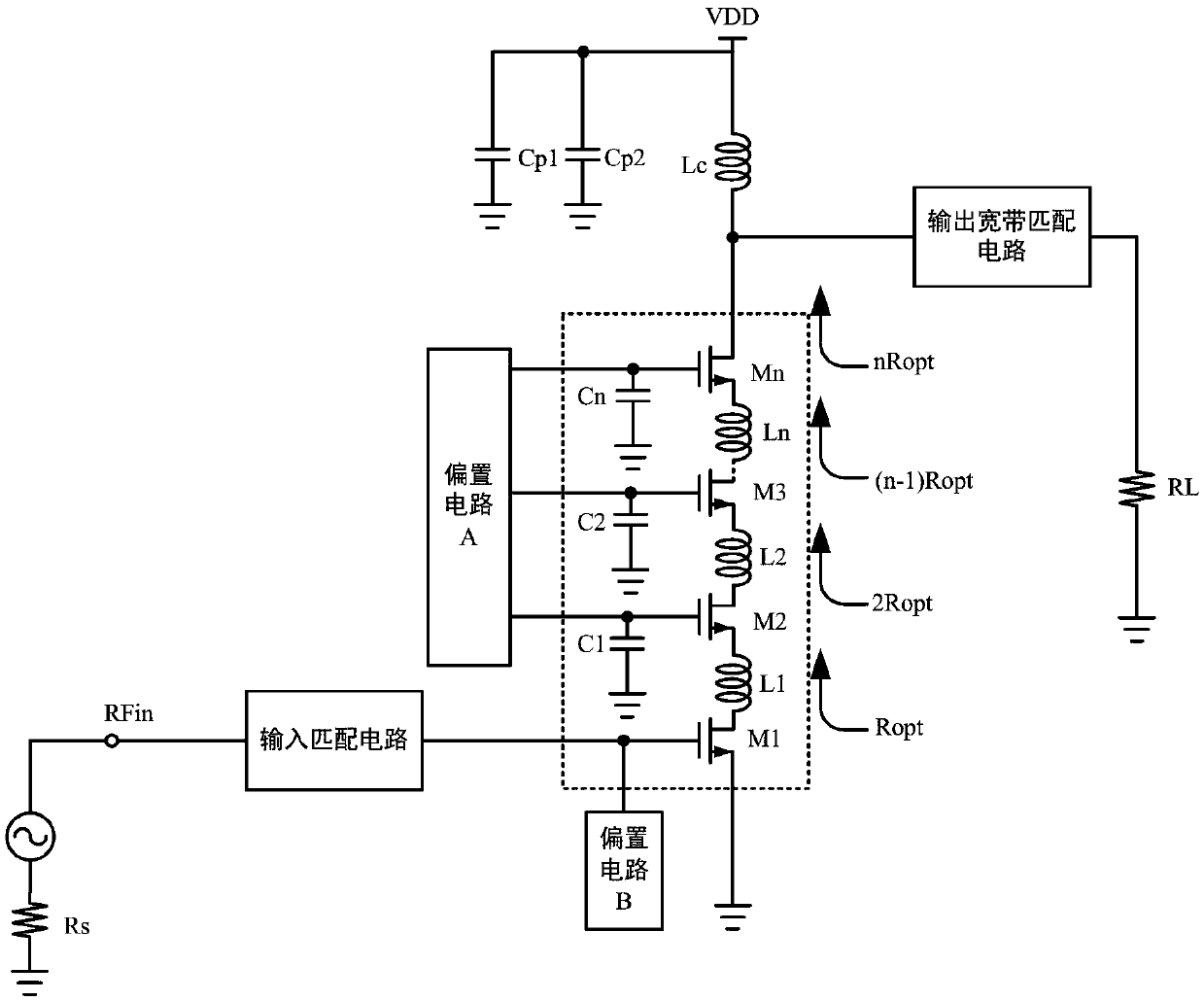
[0021] A preferred embodiment of the present invention, a stacked radio frequency power amplifier with optimal matching, the radio frequency power amplifier includes an input matching circuit, an output broadband matching circuit, a bias circuit A, a bias circuit B, and at least two A power amplifying circuit in which the drains and sources of two transistors are connected and stacked through inductances, inductances L1 to Ln in the figure; wherein, the radio frequency signal source RFin is connected to the gate of the transistor M1 at the bottom of the power amplifying circuit through the input matching circuit , the bias circuit B is connected to the gate of the bottom transistor M1; the bias circuit A is connected to the gates of other transistors in the power amplifier circuit except the bottom transistor, that is, transistors M2 to Mn; The source of the bottommost transistor M1 is directly grounded, and the gates of the remaining transistors are connected to the ground thr...


PUM


Abstract

The invention discloses a stacked radio frequency power amplifier with optimal matching, comprising an input matching circuit, an output bandwidth matching circuit, a biasing circuit A, a biasing circuit B, and a power amplifying circuit formed by stacking at least two transistor drain and source electrodes through inductors; a signal source is connected with a gate electrode of a transistor in the bottommost layer of the power amplifying circuit through the input matching circuit, and the biasing circuit B is also connected with the gate electrode; the biasing circuit A is connected with gate electrodes of remaining transistors of the power amplifying circuit, and these gate electrodes are grounded through connecting gate capacitors; a drain electrode of a transistor in the uppermost layer is connected with a load through the output bandwidth matching circuit. This circuit not only provides an improvement in the output-grade voltage withstand capacity and current drive capacity of the radio frequency power amplifier and an improvement in the output impedance of the power amplifier, but also provides an improvement in the overall linearity of the power amplifier.

Description

technical field [0001] The invention relates to a power amplifier, in particular to a radio frequency power amplifier. Background technique [0002] As an important component of the transceiver in the modern wireless communication system, the RF power amplifier is mainly used to amplify the low-power RF electrical signal without distortion, and radiate it through the antenna for information communication. [0003] The RF power amplifier structure includes various forms, such as linear power amplifier structure and saturated power amplifier structure, etc. With the different modulation methods used in wireless communication systems, the corresponding RF power amplifiers are different. For example, in order to provide high-speed data stream services, modern communication systems use modulation methods such as QPSK, which requires that the power amplifier used in the system must have high linearity and efficiency. [0004] In addition, as the functional modules of portable dev...

Claims


Application Information

Patent Timeline
IPC IPC(8): H03F1/32H03F1/42H03F1/52H03F1/56H03F3/19H03F3/21H03F3/24
CPCH03F1/3205H03F1/42H03F1/523H03F1/56H03F3/19H03F3/21H03F3/245
Inventor 林俊明章国豪张志浩余凯
Owner GUANGDONG UNIV OF TECH
Why Eureka
Try Eureka