Catalytic cracking catalyst regeneration method and device

A regeneration equipment and catalytic cracking technology, which is applied in catalyst regeneration/reactivation, physical/chemical process catalyst, metal/metal oxide/metal hydroxide catalyst, etc., can solve the problem of poor fluidization effect, high price of platinum, To solve problems such as limited resources, to improve product distribution, achieve smooth operation, and reduce carbon content

Active Publication Date: 2016-04-27
CHINA PETROLEUM & CHEM CORP +1
View PDF6 Cites 3 Cited by
  • Summary
  • Abstract
  • Description
  • Claims
  • Application Information

AI Technical Summary

Problems solved by technology

[0003] From the point of view of the existing technology, most of the traditional CO combustion aids use platinum as the active component. Platinum is expensive and has limited resources. Moreover, the other main disadvantage of the traditional noble metal-supported CO combustion aids is that the loaded noble metals are exposed to high temperature water vapor. It is easy to condense and deactivate, so it is necessary to continuously replenish new combustion accelerants; secondly, the carrier is mostly irregular powdery oxides, whose physical properties do not match the cracking catalyst, and the fluidization effect during use is not good, resulting in large losses
Setting a buffer zone or turbulent zone or adding fresh air can alleviate the dilute-phase overheating to a certain extent, but it cannot fundamentally solve the problem of dilute-phase overheating

Method used


Image

  • Catalytic cracking catalyst regeneration method and device

Examples


Embodiment 1-3

[0052] This example is used to illustrate the effect of the catalytic cracking catalyst regeneration method and equipment provided by the present invention.

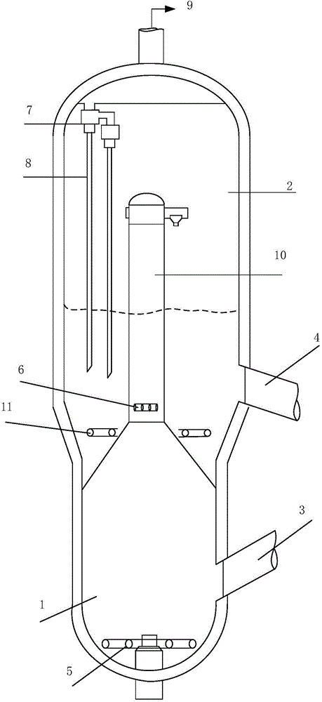
[0053] Using vacuum residue as raw material, the catalytic cracking catalyst is MLC-500, and the test is carried out on a medium-sized riser reactor. The structure of the regenerator is as figure 1 As shown, the spent catalyst from the inclined tube 3 of the spent catalyst enters the coke tank 1, and burns in contact with the oxygen-containing gas from the first main air distributor 5, and the semi-regenerated catalyst and CO produced are transported through the delivery pipe 10, and the methanol Entering the lower part of the delivery pipe 10 through the methanol distributor 6, CO contacts with methanol and continues to burn to generate CO 2 , transported together with the semi-regenerated catalyst to the middle and lower part of the catalyst dense-phase area of ​​the second regenerator 2 through the delivery pipe 10, ...


PUM


Abstract

The invention relates to a catalytic cracking catalyst regeneration method and a catalytic cracking catalyst regeneration device. The method comprises the following steps: (1) a spent catalyst contacts a first oxygen-containing gas, and coke burning is carried out; (2) a mixture obtained after coke burning contacts methanol, and combustion is carried out; and (3) the mixture obtained after combustion contacts a second oxygen-containing gas, and coke-burning regeneration is continued. The regeneration device comprises a coke burning tank and a regenerator. The inner space of the regenerator is divided into a catalyst dense phase zone positioned in the lower part and a catalyst dilute phase zone positioned in the upper part. The top of the coke burning tank is communicated with the catalyst dilute phase zone of the regenerator through a delivery pipe, such that the mixture obtained through the coke burning process in the coke burning tank can be delivered to the regenerator. A methanol distributor is arranged in the delivery pipe, and is used for introducing methanol into the delivery pipe. With the method provided by the invention, regeneration device local overheating and over-temperature phenomena caused by dilute phase tail burning can be avoided, such that regeneration device stable operation can be realized.

Description

technical field [0001] The invention relates to a catalytic cracking catalyst regeneration method and catalytic cracking catalyst regeneration equipment. Background technique [0002] Catalytic cracking is the most important processing technology for lightening heavy oil in refineries. During the catalytic cracking process, heavy oil is cracked into gas and light hydrocarbons on the surface of the catalyst, and at the same time, carbon deposits appear on the surface of the catalyst, which leads to a significant decline in activity. In order to restore the cracking activity of the catalyst and provide the required heat, the coke-deposited catalyst is sent to the regenerator after the reaction to burn off the coke attached to the catalyst and restore the activity of the catalyst. Coke combustion will release a large amount of CO 2 and CO. A large number of industrial data show that the dilute phase space for regeneration is very large, and the residence time of the flue gas ...

Claims


Application Information

Patent Timeline
Patent Type & Authority Applications(China)
IPC IPC(8): B01J38/12B01J38/20B01J23/92
Inventor 魏晓丽陈学峰袁起民
Owner CHINA PETROLEUM & CHEM CORP
Why Eureka
Try Eureka