Quick laser scanning and cutting method

A fast scanning and laser technology, applied in the direction of laser welding equipment, welding equipment, metal processing equipment, etc., can solve the problems of long time, low cutting efficiency, etc., to increase the average speed, reduce lifting and empty movement, and shorten the length Effect

Active Publication Date: 2016-04-27
上海柏楚电子科技股份有限公司
View PDF7 Cites 12 Cited by
  • Summary
  • Abstract
  • Description
  • Claims
  • Application Information

AI Technical Summary

Problems solved by technology

This kind of cutting method will spend more time waiting

Method used


Image

  • Quick laser scanning and cutting method
  • Quick laser scanning and cutting method
  • Quick laser scanning and cutting method

Examples


Embodiment

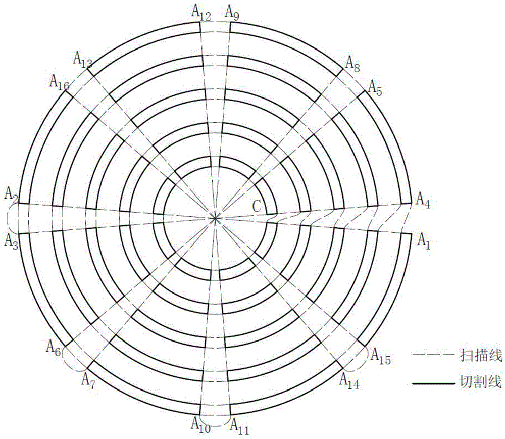
[0030] Such as image 3 As shown, the existing cutting method is: take a single fan graphic as a unit, and cut one fan at a time. First, the cutting head moves to the starting point of a fan graphic, and then follows the cutting. After cutting a fan, the cutting head lifts up. , move to the starting point of the next fan graphic, and then follow the cutting, and then repeat the above actions until all the graphics are cut. This cutting method spends more time on the moving and following actions of the cutting head, and the cutting efficiency lower.

[0031] In the present invention, cutting such as image 3 The graphical approach shown below combines the image 3 Example progress description: Step 1: First input in the graphics processing software image 3 The solid line graph in; the second step: the solid line graph is processed by the graphics processing software to obtain the following image 3 The scanning cutting diagram shown, in which the solid line is the cutting ...


PUM


Abstract

The invention relates to the field of laser cutting, in particular to a quick laser scanning and cutting method. The method comprises graphic processing software for acquiring graphic processing, machining control software for controlling a computer numerical control (CNC) system, the CNC system for controlling a machine tool servo and a laser device, a field programmable gate array (FPGA) system for processing and transferring signals, the servo for controlling a machine tool to move and the laser device which is used for producing lasers to carry out cutting and is provided with a pulse width modulation (PWM) switching system. The quick laser scanning and cutting method is characterized in that the method comprises the following steps that starting is carried out, a graph is input, a scanning and cutting pattern is generated, a position comparison and output instruction is generated, machining is started, position comparison is conducted, an output instruction is carried out, and stopping is conducted. Compared with the prior art, cutting and air moving paths of machining motion are optimized through a cutting line scanning mode, acceleration times and deceleration times in the motion process are decreased effectively, and the average speed of cutting and the average speed of air moving are increased; accordingly, the cutting motion time and the air moving motion time are shortened, and the purpose of quick cutting is achieved.

Description

technical field [0001] The invention relates to the field of laser cutting, in particular to a laser fast scanning cutting method. Background technique [0002] At present, in the field of laser processing technology, the general process of cutting is: before cutting, set the cutting height 1-2mm in advance, keep following the board surface at this height during cutting, after cutting a figure, lift the cutting head 10-20mm, Then the cutting head moves to the starting point of the next graphic, and then moves down to follow and cut. Such a cutting method will spend more time waiting for the idle movement, and the cutting efficiency is low. Contents of the invention [0003] In order to overcome the deficiencies of the prior art, the present invention designs a laser fast scanning cutting method that can reduce idle time and wait time. [0004] In order to achieve the above purpose, a method of laser fast scanning cutting is designed, including graphics processing softwar...

Claims


Application Information

Patent Timeline
IPC IPC(8): B23K26/38B23K26/0622B23K26/08
CPCB23K26/08B23K26/38
Inventor 代田田龚澜希
Owner 上海柏楚电子科技股份有限公司
Why Eureka
Try Eureka