A High-Power Millimeter-Wave Broadband Mode Converter Based on Continuous Grating Structure

A mode conversion and grating structure technology, which is applied to waveguide-type devices, connecting devices, antennas, etc., can solve the problems of easy breakdown of grating mirrors, low output mode purity, discontinuous grating mirrors, etc., to facilitate heat dissipation and design. Cooling structure, high purity output mode, simple and compact structure

Inactive Publication Date: 2018-12-18
UNIV OF ELECTRONICS SCI & TECH OF CHINA
View PDF0 Cites 0 Cited by
  • Summary
  • Abstract
  • Description
  • Claims
  • Application Information

AI Technical Summary

Problems solved by technology

However, whether it is a Vlasov-type quasi-optical mode converter or a Denisov-type quasi-optical mode converter, only a single frequency point can be achieved.
In 2000, V.I.Belovsov of the Russian Institute of Applied Physics and others realized TE by using non-quadratic mirrors, grating mirrors with jumping platforms, and matching mirrors. 01 -TEM 00 Broadband conversion of modes [V.I. Belousovs, A.A. Bogdashov, A.V. Chirkov G.G. Denisov, TE 01 -TEM 00 Quasi-Optical Mode Converter, International Journal of Infrared and Millimeter Waves, 2000,21(2):187-192], due to the presence of jumping platforms, there is discontinuity in the grating mirror, which makes the grating mirror prone to shock under high power conditions. Put on
In addition, the transformation structure also has shortcomings such as low purity of the output mode and bulky volume.

Method used


Image

  • A High-Power Millimeter-Wave Broadband Mode Converter Based on Continuous Grating Structure
  • A High-Power Millimeter-Wave Broadband Mode Converter Based on Continuous Grating Structure
  • A High-Power Millimeter-Wave Broadband Mode Converter Based on Continuous Grating Structure

Examples


Embodiment Construction

[0027] The patent will be further explained below in conjunction with the drawings.

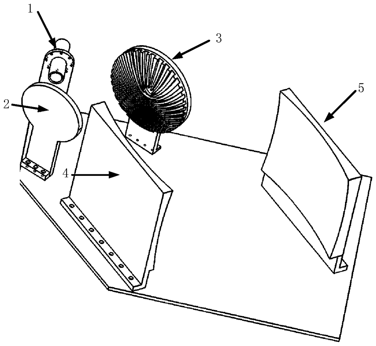
[0028] A high-power millimeter-wave broadband mode converter based on a continuous grating structure includes: a circular waveguide radiator (1), a matching mirror (2), a polarization grating mirror (3), and a phase correction system, wherein the phase correction system consists of two sides The phase correction mirrors (4) and (5) are composed, and the above components are all placed in the same metal cavity.

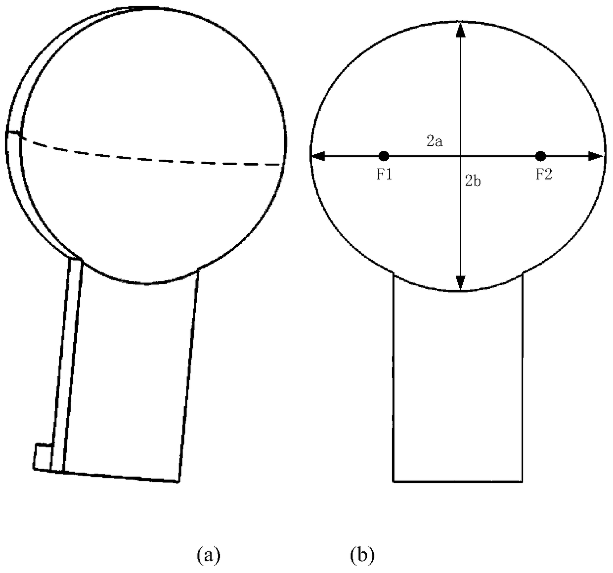
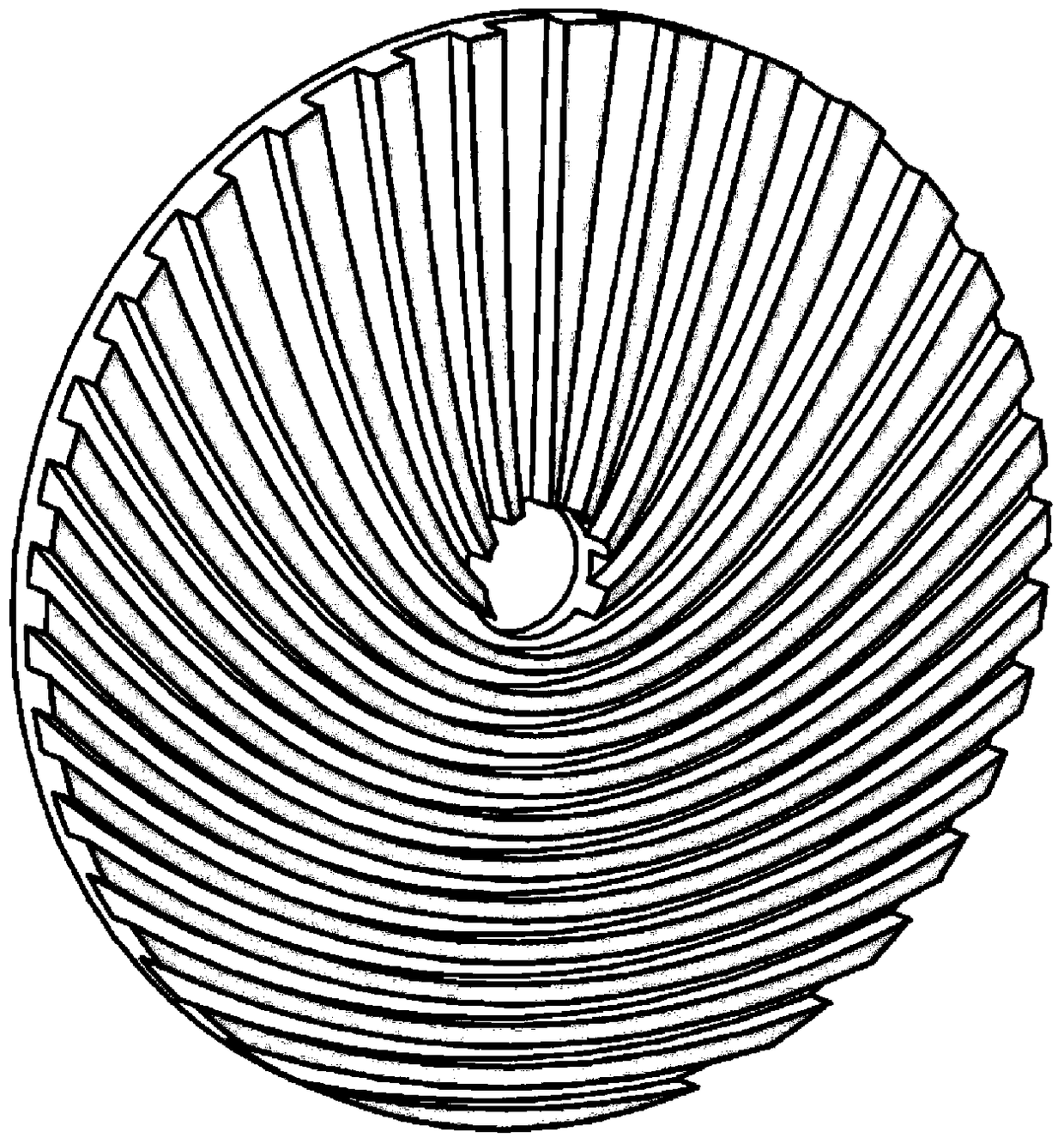
[0029] The radius of the circular waveguide radiator is equal to the high-power millimeter wave TE 0,1 Mode-TEM 00 The radius of the output port of the upstream device connected to the mode converter of the mode; the matching mirror is an ellipsoidal mirror, and its mirror direction is at an angle of 45 degrees with the axis of the open circular waveguide; the polarized grating mirror is a continuous variable-period reflection with a central opening Grating mirror, the normal of the polari...


PUM


Abstract

The invention discloses a high-power millimeter-wave broadband mode converter based on a continuous grating structure, which belongs to the field of microwave transmission of vacuum components. The mode converter includes a circular waveguide radiator, a matching mirror, a polarization grating mirror and a phase correction system. The TE0,1 mold emitted from the circular waveguide radiator into space has a curved wavefront, which is converted into a quasi-planar electromagnetic wave with a suitable beam size after passing through a parabolic mirror. The continuous variable period grating mirror placed behind the ellipsoidal mirror converts quasi-plane waves with no fixed polarization direction and symmetrical field strength distribution into linearly polarized waves with a single polarization direction and strong field strength distribution in the middle and weak at both ends. Finally, the beam spot size and phase of the obtained linearly polarized wave are adjusted and corrected by the phase correction system to generate a TEM00 mode (Gaussian beam) with a specific beam spot size, and complete the conversion of the circular waveguide TE0,1‑TEM00 mode. The invention has the advantages of wide frequency band, high power capacity, compact structure and the like.

Description

Technical field [0001] The invention belongs to the field of microwave transmission of vacuum components, and specifically relates to a high-power millimeter-wave broadband mode converter based on a continuous grating structure, which is used to transfer TE output from a gyrotron 0,1 Mode conversion to TEM suitable for air propagation 00 mold. Background technique [0002] High-power millimeter waves have a wide range of applications in scientific research fields such as long-distance high-resolution radar, electron cyclotron resonance heating, super jammers, accelerators, fine ceramic sintering, material surface treatment, plasma chemistry, etc. The gyro traveling wave tube has the characteristics of high power and wide frequency band, and is an ideal power source in the millimeter wave and sub millimeter wave frequency band. In order to reduce the working loss of the device and improve the efficiency of standing wave interaction, the high-power cyclotron traveling wave tube usu...

Claims


Application Information

Patent Timeline
Patent Type & Authority Patents(China)
IPC IPC(8): H01Q15/16H01P5/10
CPCH01P5/10H01Q15/16
Inventor 吴泽威李浩浦友雷李天明
Owner UNIV OF ELECTRONICS SCI & TECH OF CHINA
Why Eureka
Try Eureka