Optical comb repetition frequency doubling system based on all-pass phase-lock optical ring resonator

A ring cavity and optical fiber technology, applied in the field of measurement, can solve the problems of difficult self-imaging conditions in the time domain, and achieve the effects of small phase noise, small energy fluctuations, and high compression ratio

Inactive Publication Date: 2016-04-27
TSINGHUA UNIV
View PDF4 Cites 4 Cited by
  • Summary
  • Abstract
  • Description
  • Claims
  • Application Information

AI Technical Summary

Problems solved by technology

Although this method can achieve any multiple of repetition frequency doubling, it requires a specific dispers

Method used


Image

  • Optical comb repetition frequency doubling system based on all-pass phase-lock optical ring resonator
  • Optical comb repetition frequency doubling system based on all-pass phase-lock optical ring resonator
  • Optical comb repetition frequency doubling system based on all-pass phase-lock optical ring resonator

Examples


Embodiment Construction

[0010] The implementation of the present invention will be described in detail below in conjunction with the drawings and examples.

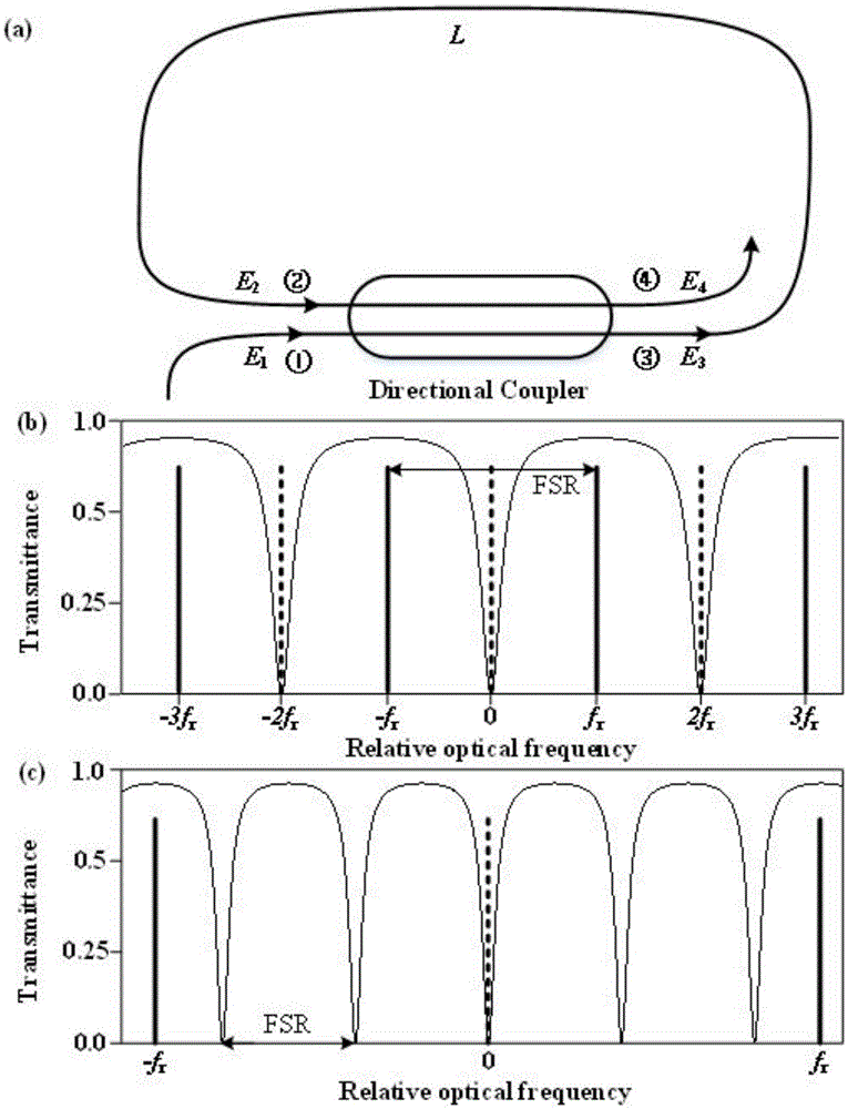
[0011] The principle of the present invention is as figure 1 shown. figure 1 (a) A schematic diagram of the structure of the all-pass fiber ring cavity is given, which consists of a single-mode fiber and a fiber directional coupler with adjustable coupling ratio. Assuming that the loss of the fiber directional coupler is independent of the coupling ratio, then by figure 1 (a) It can be obtained that the light intensity loss γ of the fiber directional coupler is:

[0012] |E 3 | 2 +|E 4 | 2 =(1-γ)(|E 1 | 2 +|E 2 | 2 ),(1)

[0013] where E i is the complex optical field intensity of the i-th port of the fiber directional coupler. E can be obtained from the interaction between the coupled modes 3 and E 4 expression for:

[0014] E 3 = ( 1 ...


PUM


Abstract

The invention relates to an optical comb repetition frequency doubling system based on an all-pass phase-lock optical ring resonator. The optical comb repetition frequency doubling system comprises an all-pass optical ring resonator and an electronic phase-lock unit, wherein the all-pass optical ring resonator consists of a single mode fiber optical direction coupler with adjustable coupling ratio and an automatically controlled optical delay line. In order to realize repetition frequency doubling, the resonator length is accurately controlled to be odd numbers of optical comb semi-resonator length by the electronic phase-lock unit. Energy loss is only related to the loss of the optical ring resonator, and thus the energy efficiency is high; the phase-lock unit is simple in configuration, obtained repetition frequency doubling is small in output pulse intensity, high in adjacent longitudinal mode compression ratio, good in frequency stability and low in phase noise; and moreover, a greater repetition frequency doubling number can be obtained by cascading a plurality of repetition frequency doubling units.

Description

technical field [0001] The invention belongs to the field of measurement technology, in particular to an optical comb repetition frequency doubling system based on an all-pass phase-locked optical fiber ring cavity. Background technique [0002] The repetition frequency of the optical comb is equal to the frequency interval between two adjacent longitudinal modes of the optical comb in the frequency domain. In some application fields, since the small frequency interval will cause aliasing between the longitudinal modes and thus reduce the measurement resolution, the larger the frequency interval between the two longitudinal modes, the better, and it is best to reach the GHz level, such as absolute distance measurement, astronomical spectroscopy Calibration, gas spectroscopy, arbitrary waveform generation, and optical frequency metrology. The upper limit of the laser repetition frequency is determined by the physical cavity length of the laser, especially for the erbium-dope...

Claims


Application Information

Patent Timeline
IPC IPC(8): H01S3/067H01S3/106
CPCH01S3/06791H01S3/106
Inventor 杨丽君杨宏雷李岩尉昊赟
Owner TSINGHUA UNIV
Why Eureka
Try Eureka