
Lithium battery protection chip of integrated power metal oxide semiconductor field effect transistor (MOSFET) and charging circuit applying chip

A technology that integrates power and protection chips. It is used in battery overcharge protection, battery circuit device, battery overdischarge protection, etc. It can solve the problem of large PCB area of ​​lithium battery protection circuit, unsuitable space limitation, and integration of lithium battery protection circuit. low level issues

Inactive Publication Date: 2016-05-04
SHENZHEN ZHUORUISICHUANG TECH CO LTD
View PDF4 Cites 13 Cited by
  • Summary
  • Abstract
  • Description
  • Claims
  • Application Information

AI Technical Summary

Problems solved by technology

[0003] At present, lithium battery protection chips in the prior art generally do not have integrated power MOSFETs. Since the power MOSFETs need to occupy a very large area, the lithium battery protection circuits in the prior art need to use additional power MOSFETs on the PCB, which will The PCB area of ​​the lithium battery protection circuit is too large, which is not suitable for occasions with very small space constraints
At the same time, the integration level of lithium battery protection circuits without integrated power MOSFETs is not high, and the cost of lithium battery protection circuits cannot be further reduced

Method used


Image

  • Lithium battery protection chip of integrated power metal oxide semiconductor field effect transistor (MOSFET) and charging circuit applying chip
  • Lithium battery protection chip of integrated power metal oxide semiconductor field effect transistor (MOSFET) and charging circuit applying chip
  • Lithium battery protection chip of integrated power metal oxide semiconductor field effect transistor (MOSFET) and charging circuit applying chip

Examples


Embodiment Construction

[0011] The present invention will be described in detail below in conjunction with the accompanying drawings.

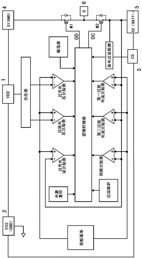
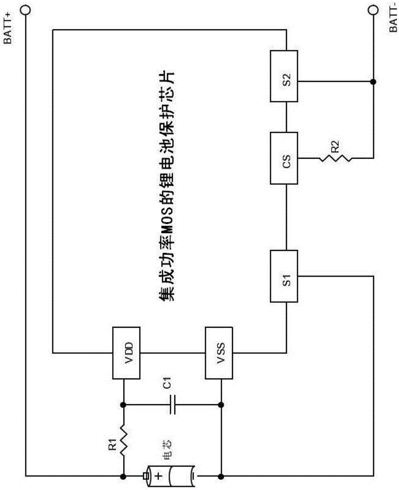
[0012] like figure 1 As shown, the lithium battery protection chip with integrated power MOSFET proposed by the present invention has six pins, which are respectively: positive power supply input terminal VDD, negative power supply input terminal VSS (GND), overcurrent detection input terminal / charger detection terminal CS , battery core negative terminal S1, charging negative terminal S2, power MOSFET drain common terminal D; and the lithium battery protection chip with integrated power MOSFET includes: logic controller, overcharge current comparator, overdischarge voltage comparator, overcharge Voltage comparator, short circuit comparator, first over-discharge current comparator, second over-discharge current comparator, power reset module, oscillator module, bandgap reference circuit, voltage divider, discharge overcurrent detection module, charging control MOSFE...


PUM

PropertyMeasurementUnit
Capacitanceaaaaaaaaaa

Abstract

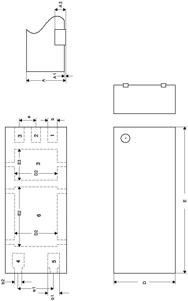
The invention relates to a lithium battery protection chip of an integrated power metal oxide semiconductor field effect transistor (MOSFET). The lithium battery protection chip is provided with six pins as follows: a positive power input end VDD, a negative power input end VSS (GND), an overcurrent detection input end / charger detection end CS, a battery core negative electrode end S1, a charging negative electrode end S2 and a power MOSFET drain common end D. The chip comprises a logic controller, an over-charging current comparator, an over-discharging voltage comparator, a short-circuit comparator, a first over-discharging current comparator, a second over-discharging current comparator, a power reset module, an oscillator module, a bandgap reference circuit, a voltage divider, a discharging overcurrent detection module, an MOSFET for charging control and an MOSFET for discharging control. The chip disclosed by the invention has protective functions of over-charging, over-discharging, overcurrent, short-circuit and the like, and the working power consumption is very low; and moreover, the area of a printed circuit board (PCB) of the chip is substantially reduced, and the chip is very suitable for various information product occasions which are very small in space limitation and require a rechargeable lithium battery to supply power for a long time. The chip adopts a small-sized package mode of DFN-5L, the chip area is further reduced, and thus, the chip cost is reduced.

Description

technical field [0001] The invention relates to the technical field of integrated circuits, in particular to a lithium battery protection chip integrating power MOSFETs and a charging circuit using the chip. Background technique [0002] In the field of lithium battery technology, lithium batteries have the advantages of small size, large capacity, light weight, no pollution, high single-cell voltage, low self-discharge rate, and many battery cycles. Generally, lithium batteries include lithium ion batteries and lithium polymer batteries. The following takes lithium-ion battery as an example to illustrate the charging and discharging process of the battery. When charging, lithium ions move from the positive electrode to the negative electrode and are embedded in the graphite layer. During discharge, lithium ions detach from the surface of the negative electrode in the graphite crystal and move to the positive electrode. Therefore, during the charging and discharging proce...

Claims


Application Information

Patent Timeline
IPC IPC(8): H02J7/00
CPCH02J7/0029H02J7/00302H02J7/00306H02J7/0034H02J7/0036
Inventor 刘陵刚申旭
Owner SHENZHEN ZHUORUISICHUANG TECH CO LTD
Learn More