
Floating body device

A floating body and inner shell technology, which is applied in transportation and packaging, special-purpose ships, warships, etc., can solve problems such as difficulty in construction, poor stability, and insufficient buoyancy, and achieve good stabilization effects, ensure stability, and improve stability. Effect

Inactive Publication Date: 2016-05-11
BEIJING GUODIAN FUTONG SCI & TECH DEV
View PDF6 Cites 0 Cited by
  • Summary
  • Abstract
  • Description
  • Claims
  • Application Information

AI Technical Summary

Problems solved by technology

Although some schemes for setting the solar power generation platform on the water surface have been disclosed in the prior art, there is no detailed introduction to the floating body structure, and the buoyancy of the floating body structure itself in the above-mentioned technical solutions is insufficient, and it is necessary to pass the tether and Most of the solutions rely on the connection with underwater anchor piles or underwater stratum structures.
Such a design method requires a lot of anchor piles at the bottom of the water, which brings great difficulty to the construction.
Moreover, it is fixed to the underwater anchor pile by means of a tether, and its stability is easily affected by water flow and wind force, and its stability is poor.

Method used


Image

  • Floating body device
  • Floating body device
  • Floating body device

Examples


Embodiment 1

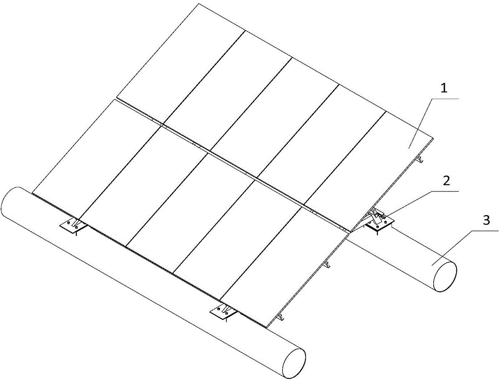
[0030] This embodiment provides a floating body device, such as figure 1 As shown, it is mainly used for fixing solar panels. Depend on figure 1 It can be seen that the solar panel assembly 1 is fixed on a set of floating device 3 through the fixing bracket 2 . The floating body device in this embodiment includes an airtight casing and a reinforcing body arranged in the airtight casing, and the rigidity of the floating body device satisfies that the maximum radial deformation does not exceed one percent of its diameter when bearing a load, and the maximum The axial deformation shall not exceed five thousandths of its length. Its mass is between 102KG and 550KG, and its length is 4000mm-8000mm. It floats on the water surface and can provide a buoyancy greater than 3.84KN. Two floating body devices form a group, and each group of floating body devices can carry 4 to 16 photovoltaic modules. The weight of the floating body device is one of the important reasons affecting the ...

Embodiment 2

[0032] This embodiment provides a floating device. On the basis of Embodiment 1, the material of the airtight shell is polymer material, and further, the material of the airtight shell is rubber or fiberglass. Such as figure 2 As shown, it is a closed hollow structure, and the reinforcing body is high-strength foam plastic. The thickness of the airtight casing in this embodiment is 3mm, which has sufficient thickness, and its material has sufficient service life.

[0033] Since the airtight casing 4 has sufficient thickness and sufficient strength, it can meet the force requirements. And because of its thicker thickness, it has a larger self-weight, so it has better floating stability.

[0034] At the same time, it also has good anti-wind and wave performance.

[0035] Such as Figure 5 and Figure 6 A force simulation analysis diagram of the floating body device in this embodiment is given. Using ANSYS14.0 software to simulate it. According to the simulation results, ...

Embodiment 3

[0037] In the floating body device in this embodiment, the airtight casing includes an airtight inner casing, an airtight outer casing, and a reinforcing body for improving the strength of the airtight casing. Such as image 3 As shown, the airtight outer casing 5 in this embodiment can be a rubber outer casing or a fiberglass outer casing obtained by covering at least one layer of fiber cloth with rubber or synthetic resin. The airtight inner casing 6 is made of steel. The reinforcing body 7 is a high-strength foam filled inside the airtight inner casing, the length of the floating body device is between 4000mm-8000mm, and the diameter is 540mm.

[0038] In this embodiment, the ratio of the length to the diameter of the floating body device with this structure is about ten times, which can effectively resist the effects of wind and water waves, and the floating body device is not easy to overturn when floating in water. Moreover, compared with the existing floating bodies, th...


PUM

PropertyMeasurementUnit
Thicknessaaaaaaaaaa
Wall thicknessaaaaaaaaaa
Thicknessaaaaaaaaaa

Abstract

The invention provides a floating body device, comprising a closed housing and a reinforcing body which is arranged in the closed housing and has certain strength. The rigidity of the floating body device satisfies that maximum radial deformation is not larger than one percent of the diameter of the device when the device bears load, maximum axial deformation quantity is not larger than 0.5% of the length of the device, and the mass of the floating body device is between 102 kg to 550 kg, and the floating body device floats in water and provides buoyancy which is larger than 3.84 KN. When the mass of the floating body device satisfies the above condition, enough force is provided to resist action of wind power or hydraulic power, so as to ensure stability of the device. Each floating body device floating in water can provide the buoyancy which is larger than 3.84 KN, and two floating body devices are a group, and each group of the floating body devices can carry 4-16 photovoltaic modules. Through simulation analysis, when the floating body devices are connected to form a net structure to support a solar power generation assembly, the floating body platform of the whole net structure can resist wind power of typhoon of about twelve grade. Therefore, the device has good stability.

Description

technical field [0001] The invention relates to the technical field of power generation equipment installation, in particular to a floating body device. Background technique [0002] Compared with the existing hydropower generation technology and solar power generation technology, hydro-solar hybrid power generation technology has significant advantages of not occupying land, low transmission cost, and high energy utilization efficiency. Therefore, this technology has also become a hot spot in the field of power industry research and development in recent years. For example, in 2011, British designers proposed the concept of floating solar cells, which can simultaneously collect wave energy and solar energy. In the same year, Israel's SolarisSynergy and France's EDFGroup also jointly developed a corrosion-resistant water solar power generation system. Currently, India is also building the country's first floating photovoltaic power station. A number of hydro-solar hybrid p...

Claims


Application Information

Patent Timeline
IPC IPC(8): B63B35/00
CPCY02E10/727
Inventor 刘振强马维丰苗文华滕济林张培林贾瑞清陈志明郭锐
Owner BEIJING GUODIAN FUTONG SCI & TECH DEV
Learn More