A treatment method for catalytic cracking regenerated flue gas

A technology for catalytic cracking and flue gas regeneration, which is applied in the direction of non-catalytic thermal cracking, cracking, petroleum industry, etc., can solve the problems of complex post-treatment of pollutants and catalyst dust, large energy recovery loss, etc., and achieve increased liquid yield, transmission Enhanced heat capacity and reduced coking effect

Active Publication Date: 2017-09-29
CHINA PETROLEUM & CHEM CORP +1
View PDF2 Cites 0 Cited by
  • Summary
  • Abstract
  • Description
  • Claims
  • Application Information

AI Technical Summary

Problems solved by technology

[0011] The purpose of the present invention is to overcome the large energy recovery loss and CO, SO X and NO X To provide a new treatment method for catalytic cracking regenerated flue gas

Method used


Image

  • A treatment method for catalytic cracking regenerated flue gas
  • A treatment method for catalytic cracking regenerated flue gas
  • A treatment method for catalytic cracking regenerated flue gas

Examples


Embodiment approach

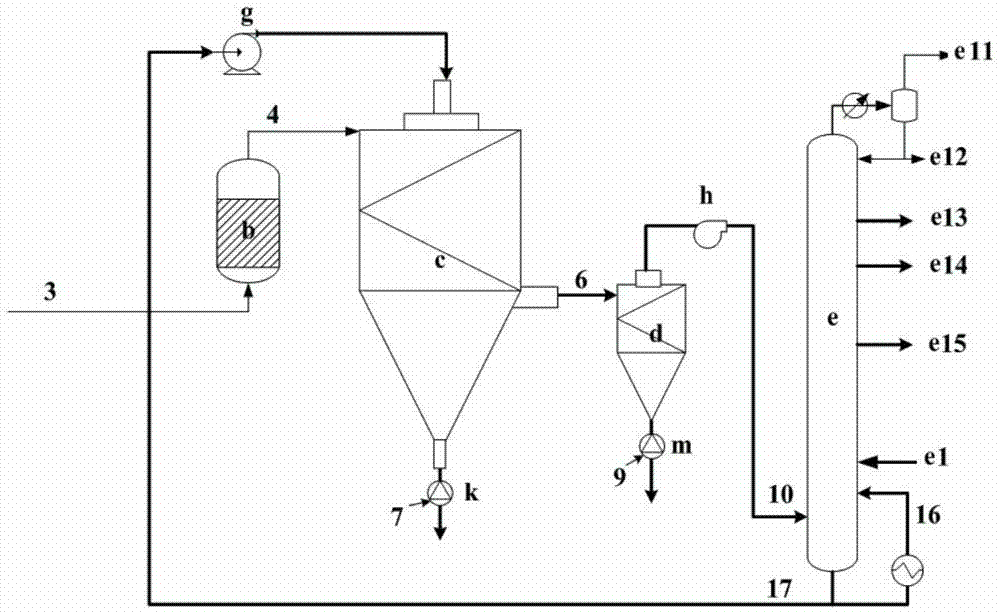
[0046] The present invention does not specifically limit the source and introduction method of the heavy oil coking raw material. For example, the heavy oil coking raw material can be various existing heavy oil raw materials that can be used for coking, and the heavy oil coking raw material can be heated by a heating furnace to After 50-400°C, it is introduced into the spray coking tower c. According to a preferred embodiment of the present invention, the heavy oil coking method further includes introducing feedstock oil into the fractionation tower e from a feedstock inlet e1 arranged below the side of the fractionation tower e, and the feedstock oil and the The bottom reflux oil is mixed at the bottom of the fractionation tower e and introduced as coking raw material 17 into the spray coking tower c for atomization, heat exchange and coking reaction. At this time, the coking raw material can be directly preheated in the fractionating tower , there is no need to additionally ...

Embodiment 1-3

[0054] Examples 1-3 are used to illustrate the treatment method of catalytic cracking regenerated flue gas provided by the present invention.

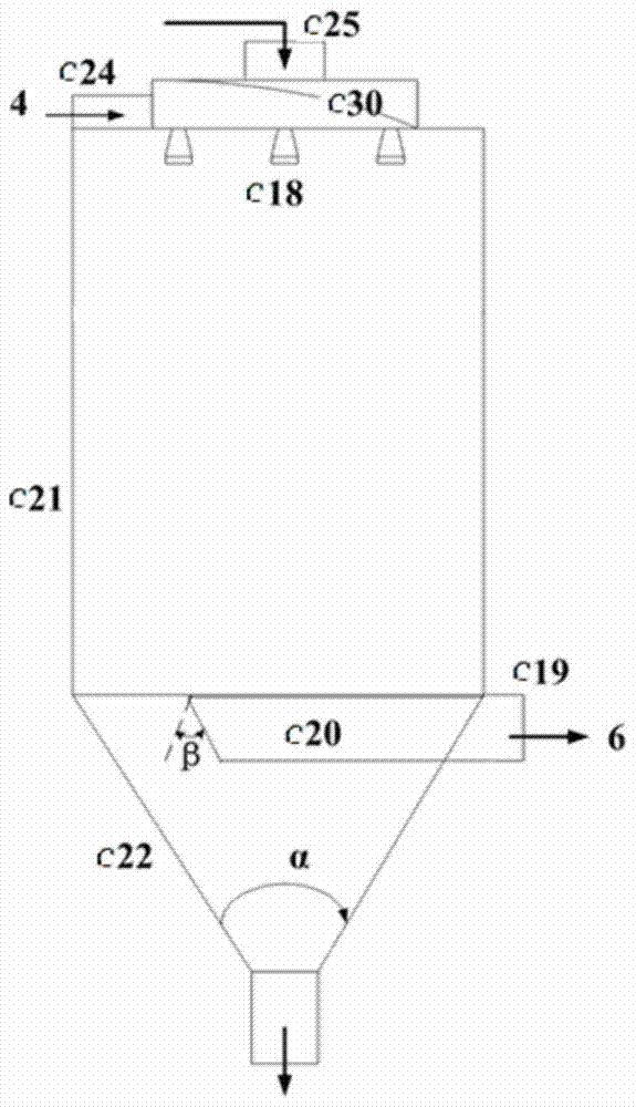
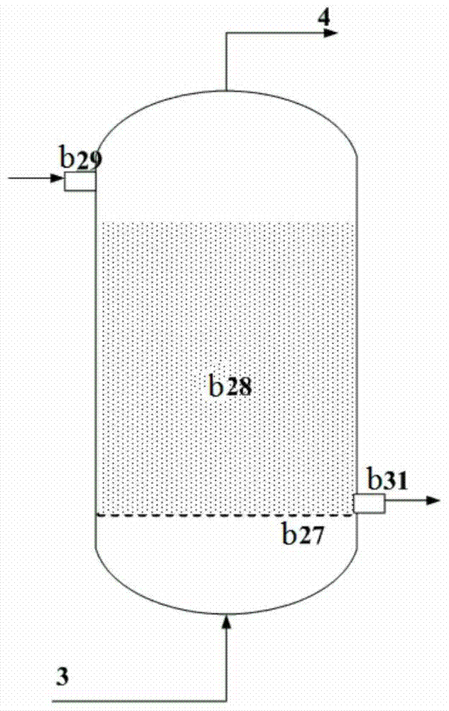
[0055] The feedstock oil is introduced into the fractionation tower e from the feedstock inlet e1 of the fractionation tower e for preheating, and the feedstock oil obtained after preheating is introduced into the spray coking tower c through the feedstock inlet c25 and atomized through the atomizing nozzle c18 to obtain Atomized liquid droplets with a liquid size of 20-500 μm, catalytic cracking regenerated flue gas 3 is deoxidized through coke reactor b, and catalytic cracking regenerated flue gas 4 (wherein the oxygen content is 0.1 volume %) after deoxidation is passed through the spray The hot air inlet c24 at the top of the coking tower c is introduced into the spray coking tower c and contacts with the above-mentioned atomized small liquid droplets to make it reach the coking temperature and carry out the coking reaction, and the...


PUM

PropertyMeasurementUnit
particle diameteraaaaaaaaaa
diameteraaaaaaaaaa

Abstract

The invention provides a treatment method for catalytic cracking regenerated flue gas. The method comprises atomizing the heavy oil coking raw material with a temperature of 50-400°C, and then mixing the atomized heavy oil coking raw material with a temperature of 490-750°C. The deoxygenated flue gas is contacted so that the atomized heavy oil coking raw material reaches the coking temperature and undergoes a coking reaction, and the deoxygenated flue gas is a gas obtained by deoxygenating the catalytic cracking regenerated flue gas. The treatment method of catalytic cracking regenerated flue gas provided by the present invention can not only utilize the kinetic energy and thermal energy of catalytic cracking regenerated flue gas to the greatest extent and save the steps of desulfurization, denitrification and dust removal of catalytic cracking regenerated flue gas, but also can reduce or even completely avoid coking In the process, the coking in the furnace tube of the heating furnace can be improved and the liquid yield can be improved, which has great industrial application prospects.

Description

technical field [0001] The invention relates to a treatment method for catalytic cracking regenerated flue gas. Background technique [0002] In the fluidized catalytic cracking (FCC) process, the raw oil and the catalyst are quickly contacted in the riser for catalytic cracking reaction, and the coke generated by the reaction is deposited on the catalyst to cause its deactivation, and the deactivated catalyst enters after stripping The regenerator performs char regeneration. The temperature of the flue gas generated by regeneration can be as high as about 700°C, and the energy taken away by it in the catalytic cracking unit can account for about a quarter of the energy consumption of the whole unit. The energy recovery efficiency of the regenerative flue gas also directly affects the energy consumption of the entire device. [0003] At present, the energy recovery method of catalytic cracking regenerated flue gas is still the combined recovery method of flue gas turbine a...

Claims


Application Information

Patent Timeline
Patent Type & Authority Patents(China)
IPC IPC(8): C10G9/36
Inventor 张翊吕庐峰侯栓弟王子军张久顺张哲民马力李学锋何金龙田志鸿刘亚林
Owner CHINA PETROLEUM & CHEM CORP
Why Eureka
Try Eureka