In-situ visualization method for cavitation behavior of fused brazing filler metal in solid liquid interface in ultrasonic-assisted brazing

A technology of solid-liquid interface and molten solder, applied in welding equipment, metal processing equipment, manufacturing tools, etc., to achieve the effect of optimizing technology and application

Active Publication Date: 2016-06-08
BEIJING UNIV OF TECH
View PDF5 Cites 10 Cited by
  • Summary
  • Abstract
  • Description
  • Claims
  • Application Information

AI Technical Summary

Problems solved by technology

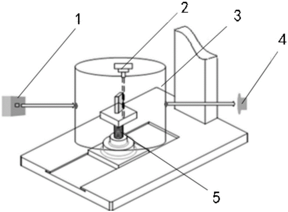
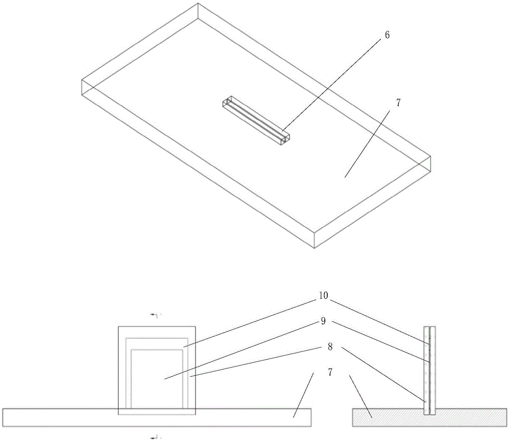
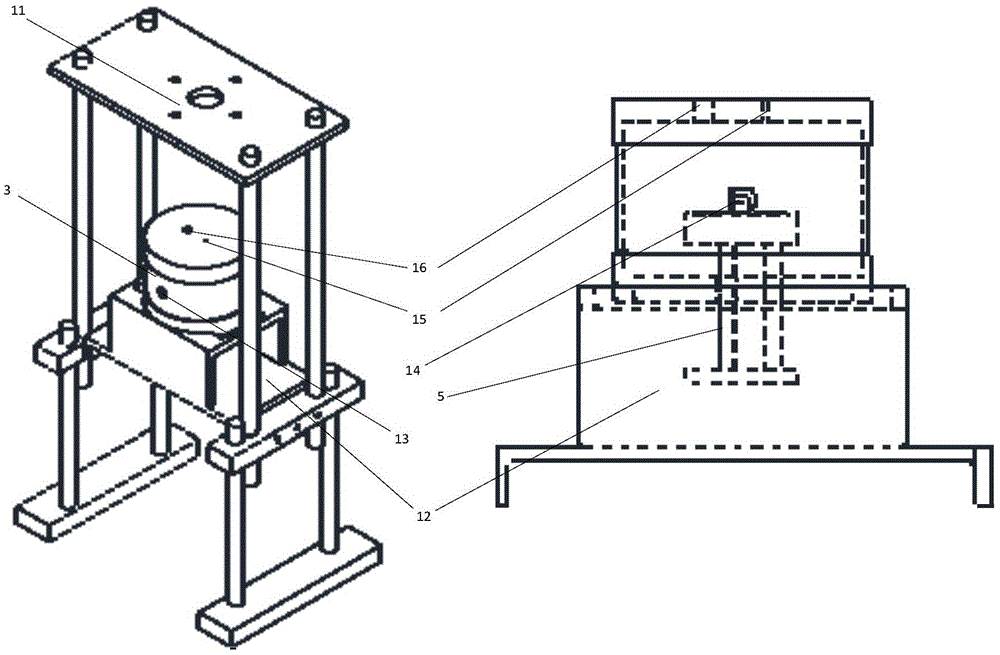
[0005] In view of the existing problems in the prior art, the present invention discloses a synchrotron radiation imaging visualization method for ultrasonic-assisted brazing solid-liquid interface molten metal hollowing behavior, which is heated by a small resistance furnace, using a resistant The high-temperature ultrasonic vibration system directly applies ultrasound to the base metal, which solves the limitation of synchrotron radiation imaging visualization of different solder alloys at the solid-liquid interface under the ultrasonic field, especially the cavitation behavior of the high-melting point solder in the solid-liquid interface under the ultrasonic field

Method used


Image

  • In-situ visualization method for cavitation behavior of fused brazing filler metal in solid liquid interface in ultrasonic-assisted brazing
  • In-situ visualization method for cavitation behavior of fused brazing filler metal in solid liquid interface in ultrasonic-assisted brazing
  • In-situ visualization method for cavitation behavior of fused brazing filler metal in solid liquid interface in ultrasonic-assisted brazing

Examples


Embodiment 1

[0052] Using the above-mentioned synchrotron radiation imaging method and device, Al-11.5Si-1.5Mg solder alloy (melting point 585°C) was selected to make an ultra-thin sample of 200 μm by sandpaper grinding, and TC4 titanium alloy was selected as the base material, and the test temperature was set At 610°C, observe the generation and distribution of bubbles at the solid-liquid interface during the heating process and after ultrasonic application. Among them, a) there are no bubbles at 0°C, and there are gaps at the interface; b) bubbles appear at 610°C when ultrasonic is applied for 10s; c) bubbles become larger and gaps decrease at 620°C when ultrasonic is applied for 60s. Such as Figure 4 Shown:

Embodiment 2

[0054] Using the above-mentioned synchrotron radiation imaging method and device, select Al-11.5Si-1.5Mg solder alloy (melting point 585°C), grind it with sandpaper to make an ultra-thin sample of 200 μm, select 1060 aluminum alloy as the base material, and set the test temperature At 600°C, observe the generation and distribution of bubbles at the solid-liquid interface during the heating process and after ultrasonic application. Among them, a) there are no bubbles at 0°C, and there are gaps at the interface; b) bubbles appear at 600°C when ultrasonic is applied for 10s; c) bubbles become larger when ultrasonic is applied for 50s at 610°C. Such as Figure 5 shown.


PUM

PropertyMeasurementUnit
melting pointaaaaaaaaaa

Abstract

The invention relates to an in-situ visualization method for the cavitation behavior of fused brazing filler metal in a solid liquid interface in ultrasonic-assisted brazing. The in-situ visualization method is suitable for the sizes of the brazing filler metal and base metal for synchrotron radiation imaging and the sandwiched coupled mode, and an ultrasonic field is applied through a high temperature-resistant ultrasonic vibration system capable of resisting 800 DEG C. The method comprises the steps of sample preparation; ultrasonic field application preparation; integral imaging equipment assembly; and visualization measurement of synchrotron radiation imaging of the cavitation behavior of the fused brazing filler metal. The method especially comprises the steps of ultrasonic field application in the high temperature environment, selection of the coupled mode of the sample base metal and the brazing filler metal and high temperature anti-oxidation treatment. The method is widely applied to the brazing filler metal of different temperatures and plays an important role in understanding and improving breaking oxidation films of the cavitation effect of ultrasonic-assisted brazing, promoting the moistening and spreading process of the brazing filler metal, revealing the acoustic-induced moistening physical mechanism of the brazing process of the brazing filler metal and the base metal (such as aluminum alloy and titanium alloy) and promoting industrial application of the ultrasonic-assisted brazing technology.

Description

technical field [0001] The invention relates to basic research on ultrasonic-assisted brazing, in particular to a synchrotron radiation imaging visualization method for ultrasonic-assisted brazing solid-liquid interface molten solder hollowing behavior. Background technique [0002] In recent years, exploratory research on ultrasonic-assisted brazing has been carried out at home and abroad, and it has been found that ultrasonic waves are used in the brazing process to promote the wetting of the solder alloy and the base metal, and achieve non-wetting or difficult-wetting interfaces under normal conditions. forced wetting. Most researchers believe that ultrasonic waves can partially remove the oxide film through the cavitation effect and acoustic flow, and promote the wetting, spreading and filling of the solder on the surface of the substrate, so that it can be realized under non-vacuum and flux-free conditions. Joining of same or dissimilar materials. However, the acousti...

Claims


Application Information

Patent Timeline
Patent Type & Authority Applications(China)
IPC IPC(8): B23K1/06B23K1/20
CPCB23K1/06B23K1/20
Inventor 李红李灿栗卓新
Owner BEIJING UNIV OF TECH
Why Eureka
Try Eureka