Superconducting magnet

A superconducting magnet and superconducting technology, applied in the direction of superconducting magnets/coils, magnetic objects, electrical components, etc., can solve the difficulties of manufacturing process, limit large-scale application, and the performance of superconducting joints cannot meet the requirements of practical applications. , to achieve high superconducting stability, not easy to quench, and improve the effect of stability

Active Publication Date: 2016-06-08
NINGBO JANSEN SUPERCONDUCTING TECH CO LTD
View PDF8 Cites 20 Cited by
  • Summary
  • Abstract
  • Description
  • Claims
  • Application Information

AI Technical Summary

Problems solved by technology

However, for more than ten years, due to the difficulty in the manufacturing process, the performance of superconducting jo

Method used


Image

  • Superconducting magnet
  • Superconducting magnet
  • Superconducting magnet

Examples


Embodiment 1

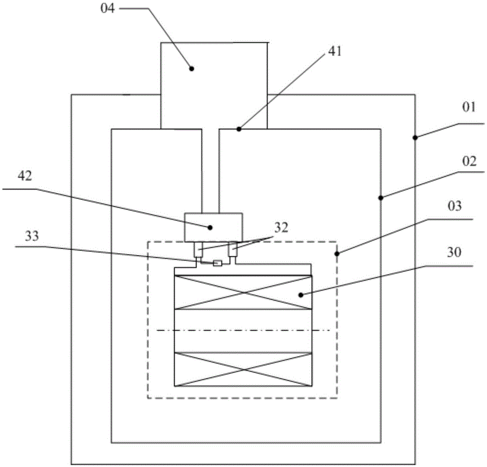
[0033] figure 1 It is a structural schematic diagram of a superconducting magnet provided by an embodiment of the present invention. Such as figure 1 As shown, the superconducting magnet includes: a vacuum container 01 , in which a cold shield 02 and a superconducting coil 30 are arranged, wherein the superconducting coil 30 is located inside the cold shield 02 .

[0034] The function of the cold shield 02 is to reduce radiation heat leakage from room temperature to the superconducting coil 30 .

[0035] In the embodiment of the present invention, the material of the vacuum container 01 may be stainless steel, of course, other non-magnetic materials other than stainless steel may also be used. In addition, the vacuum vessel 01 can be manufactured according to the relevant pressure vessel standards of our country, so that the failure of the vacuum vessel 01 can be effectively avoided and the normal operation of the superconducting magnet can be ensured.

[0036] In addition,...

Embodiment 2

[0049] It should be noted that the superconducting magnet described in Embodiment 2 has many similarities with the superconducting magnet described in Embodiment 1. For the sake of brevity, this embodiment of the present invention only describes the differences in detail. The similarities Please refer to the relevant description of Embodiment 1.

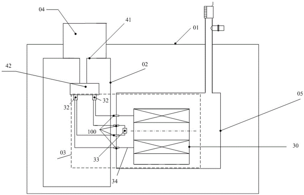
[0050] image 3 It is a schematic structural diagram of the superconducting magnet provided by Embodiment 2 of the present invention. Such as image 3 As shown, the superconducting magnet includes: a vacuum container 01 , a cold shield 02 , a superconducting coil 30 and a refrigerator 04 . In addition, the superconducting magnet may also include a liquid nitrogen container 05 . Wherein, the liquid nitrogen container 05 is arranged inside the vacuum container 01 and outside the cold shield 02 , and the liquid nitrogen submerged in the superconducting coil 30 is contained in the liquid nitrogen container 05 .

[0051] In the embodim...


PUM

PropertyMeasurementUnit
Superconducting transition temperatureaaaaaaaaaa

Abstract

The invention provides a superconducting magnet which comprises a vacuum container and a refrigerator. A cold screen and a superconducting coil are arranged in the vacuum container; superconducting wires are wound on a coil framework to form the superconducting coil, and two free ends of the superconducting coil are connected with a superconducting switch by superconducting connectors to form a closed superconducting circuit; the refrigerator is arranged on the vacuum container and comprises a primary cold head and a secondary cold head, and the primary cold head is thermally connected with the cold screen; the superconducting wires are made of superconducting materials with critical superconducting transit temperatures higher than 35 K; the superconducting connectors are made of superconducting welding flux with a low melting point, can be cooled by the aid of the secondary cold head or cooling media and accordingly can be assuredly in superconducting states. Compared with low-temperature closed-loop superconducting magnets in the prior art, the superconducting magnet has the advantage of high superconducting stability.

Description

technical field [0001] The invention relates to the technical field of superconducting magnets, in particular to a superconducting magnet operating in a closed loop, which can be used to manufacture nuclear magnetic resonance imaging superconducting magnets, magnetic separation superconducting magnets, sewage treatment superconducting magnets, superconducting energy storage devices, etc. Utility device. Background technique [0002] In existing practical superconducting magnets, such as nuclear magnetic resonance imaging superconducting magnets, superconducting coils are generally made of niobium-titanium superconducting wires, and liquid helium is generally used as a cooling medium. Niobium-titanium alloy is a low-temperature superconducting material, and its critical superconducting transition temperature is about 9K, while the boiling point of liquid helium at 1 atmosphere is 4.2K, and the difference between the two temperatures is less than 5K, which is easily caused by ...

Claims


Application Information

Patent Timeline
IPC IPC(8): H01F6/00H01F6/04H01F6/06
CPCH01F6/00H01F6/04H01F6/065
Inventor 胡倾宇郑杰莫耀敏段训琪任国峰黄志龙干明明
Owner NINGBO JANSEN SUPERCONDUCTING TECH CO LTD
Why Eureka
Try Eureka