
Horizontal gradually-pressurizing direct-current electric field sludge drying device

A direct current electric field and sludge drying technology, which is applied in sludge treatment, water/sludge/sewage treatment, dehydration/drying/thickened sludge treatment, etc., can solve the problem of not configuring filter belts, and achieve reliable constraints, running smooth effect

Inactive Publication Date: 2016-06-15
江苏百新环境工程有限公司
View PDF9 Cites 2 Cited by
  • Summary
  • Abstract
  • Description
  • Claims
  • Application Information

AI Technical Summary

Problems solved by technology

[0003] The present invention mainly aims at the disadvantages of using constant pressure dehydration under the direct current electric field in the prior art, and the problem that the filter belt of insulating material is interposed between the positive and negative electrodes to increase the voltage drop, and proposes a dehydration process with wet sludge in the dehydration zone. The process adopts a step-by-step method to apply pressure, and there is no filter belt between the positive and negative electrodes in the structure, a horizontal gradually pressurized DC electric field sludge drying device

Method used


Image

  • Horizontal gradually-pressurizing direct-current electric field sludge drying device
  • Horizontal gradually-pressurizing direct-current electric field sludge drying device
  • Horizontal gradually-pressurizing direct-current electric field sludge drying device

Examples


Embodiment Construction

[0022] In the following, the present invention will be further explained based on the drawings and the embodiments.

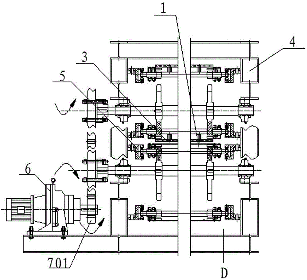
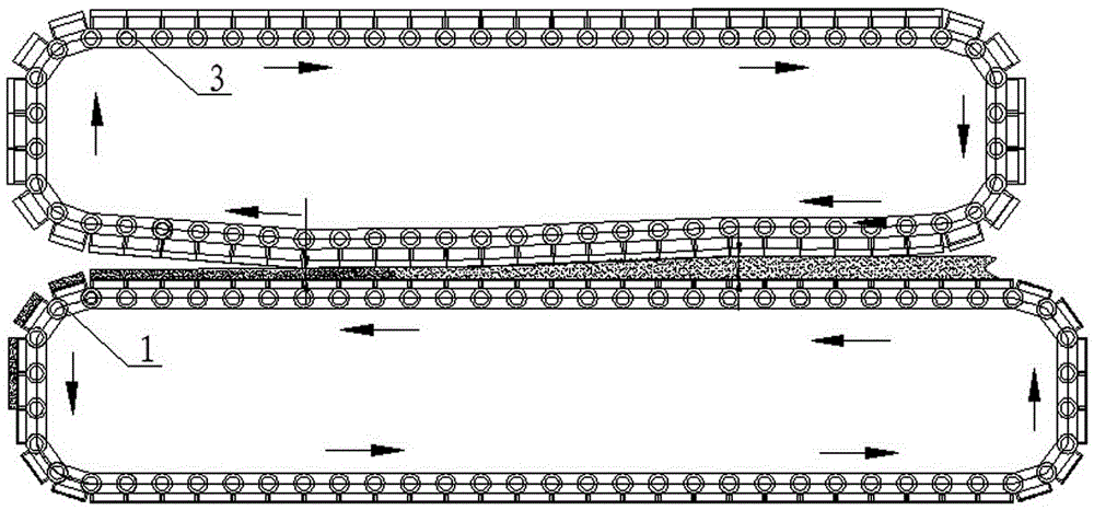
[0023] figure 1 The horizontal gradually pressurized DC electric field sludge drying device shown is supporting a daily processing capacity of 20,000 m 3 An embodiment of a municipal sewage treatment plant for sludge dewatering. The structural feature of the device is embodied in the use of built-in guide rails 5 to limit the upper crawler 3 and the lower crawler 1 to cyclically drive in a determined track. Because the distance between the upper and lower rails 5 is in a transverse wedge shape, a progressive pressurization structure of the upper crawler 3 relative to the lower crawler 1 is formed. Under the condition of DC electric field, this structure continuously and orderly increases the pressing force as the moisture content of the wet sludge being pressed decreases. On the other hand, the electron flow hits the water wall of the cell water in the wet sludge,...


PUM


Abstract

The invention discloses a horizontal gradually pressurized DC electric field sludge drying device, which comprises a lower crawler, a distributor, an upper crawler, a frame, a guide rail, a transmission mechanism, a flat brush, an unloader, a flusher and a cleaner . The guide rails are divided into two layers. The guide rails fixedly connected on both sides of the upper layer of the frame are curved straight rails, and the guide rails fixedly connected on both sides of the lower layer of the frame are flat straight rails. The vertical distance between the upper and lower layers of guide rails gradually increases from right to left. Minus, the upper crawler is driven by the guide rails located on the upper layer, and the lower crawler is driven by the guide rails located on the lower layer, thus forming a step-by-step supercharging structure. In the present invention, wet sludge is directly clamped between the upper crawler and the lower crawler which are respectively connected to the positive and negative poles of the DC electric field. There is no filter belt in the pressing dehydration area, so there is no voltage drop problem, which greatly optimizes the pressing environment, improves dehydration efficiency, and saves waste. Energy, improve the safety performance of the equipment, the most important thing is to greatly increase the biscuitization degree of the mud produced, and reduce the energy consumption of the dehydration system.

Description

Technical field [0001] The present invention relates to the field of environmental protection devices, especially to the field of sludge drying devices. Specifically, the present invention relates to a wet sludge drying device used for urban domestic sewage and industrial sewage treatment, especially a horizontal structure Gradually pressurized DC electric field sludge drying device. Background technique [0002] With the implementation of the national environmental protection policy, all localities generally attach importance to the advanced treatment of urban domestic sewage and industrial sewage. A batch of sewage treatment plants have been built, equipped with a large number of equipment, and a large-scale sewage treatment capacity has been initially formed. The by-product left after sewage treatment is wet sludge. The gelatinous wet sludge has a moisture content of 80-90%, and it is difficult to achieve the expected drying index with conventional dehydration methods. Accord...

Claims


Application Information

Patent Timeline
Patent Type & Authority Applications(China)
IPC IPC(8): C02F11/12
CPCC02F11/121C02F2201/002C02F2303/06
Inventor 杨淑兵张宪如方世峰张慧
Owner 江苏百新环境工程有限公司
Learn More