Ignition bridge with lattice-shaped energy-containing thin film

A grid-shaped, ignition bridge technology, applied in the direction of offensive equipment, fuzes, etc., can solve the problems of heat energy and plasma not being concentrated in the vertical direction, slowing down the rate of energy vertical diffusion, reducing energy utilization and conversion efficiency, etc., to achieve Improve energy utilization and energy conversion efficiency, reduce energy diffusion and loss, and accelerate the diffusion speed

Inactive Publication Date: 2016-06-22
UNIV OF ELECTRONIC SCI & TECH OF CHINA
View PDF4 Cites 8 Cited by
  • Summary
  • Abstract
  • Description
  • Claims
  • Application Information

AI Technical Summary

Problems solved by technology

But there are the following defects at the same time: First, the diffusion, interpenetration, and even pre-reaction between different components are prone to occur between the middle layer and the layer of the composite energetic reaction multilayer film, thereby forming an interface layer at the contact surface, which is harmful to matter and energy. The diffusion has a certain blocking effect, and with the increase of the storage time, the thickness of the interface layer increases, resulting in the slowdown of the longitudinal diffusion transfer rate of energy (heat energy) during the ignition process, the increase of the ignition delay time, and the decrease of the total output energy; the second , the current density passing through the ignition bridge region increases instantaneously during ignition, heat is rapidly generated and diffuse

Method used


Image

  • Ignition bridge with lattice-shaped energy-containing thin film
  • Ignition bridge with lattice-shaped energy-containing thin film
  • Ignition bridge with lattice-shaped energy-containing thin film

Examples


Embodiment

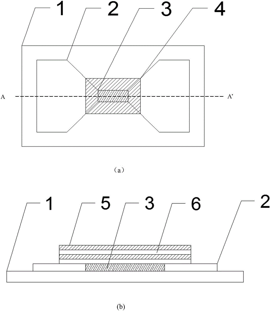
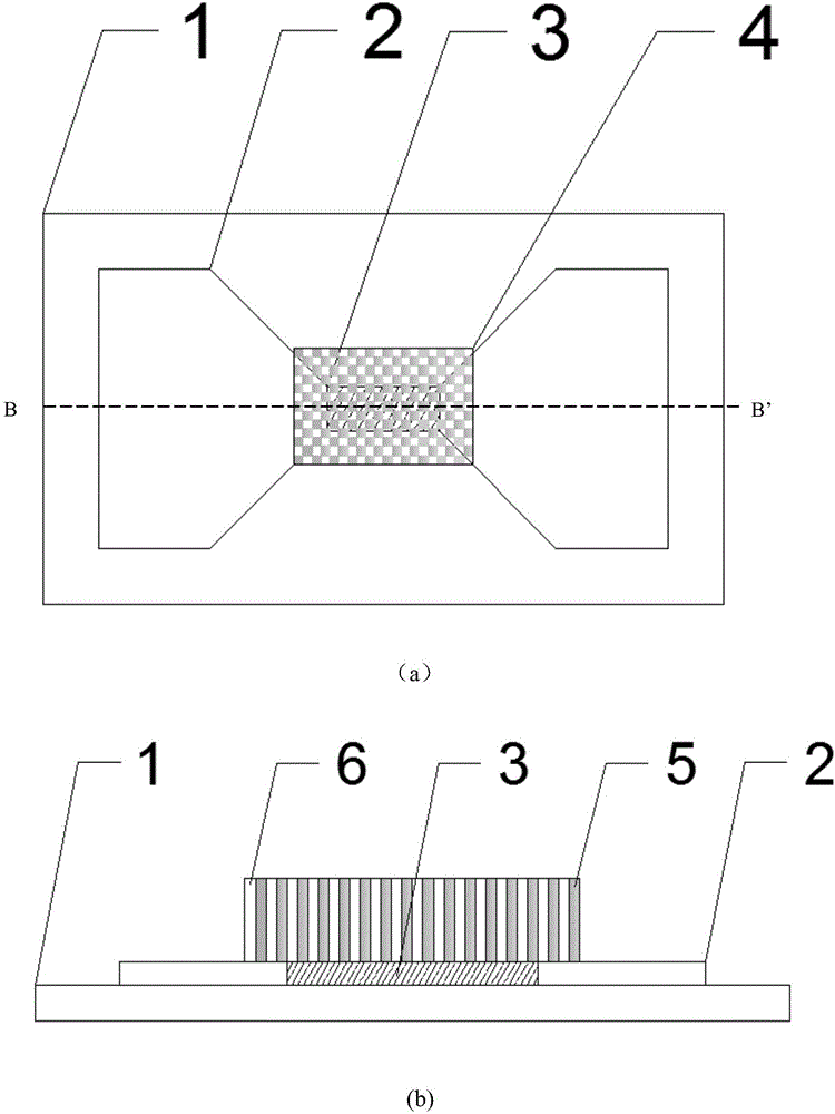
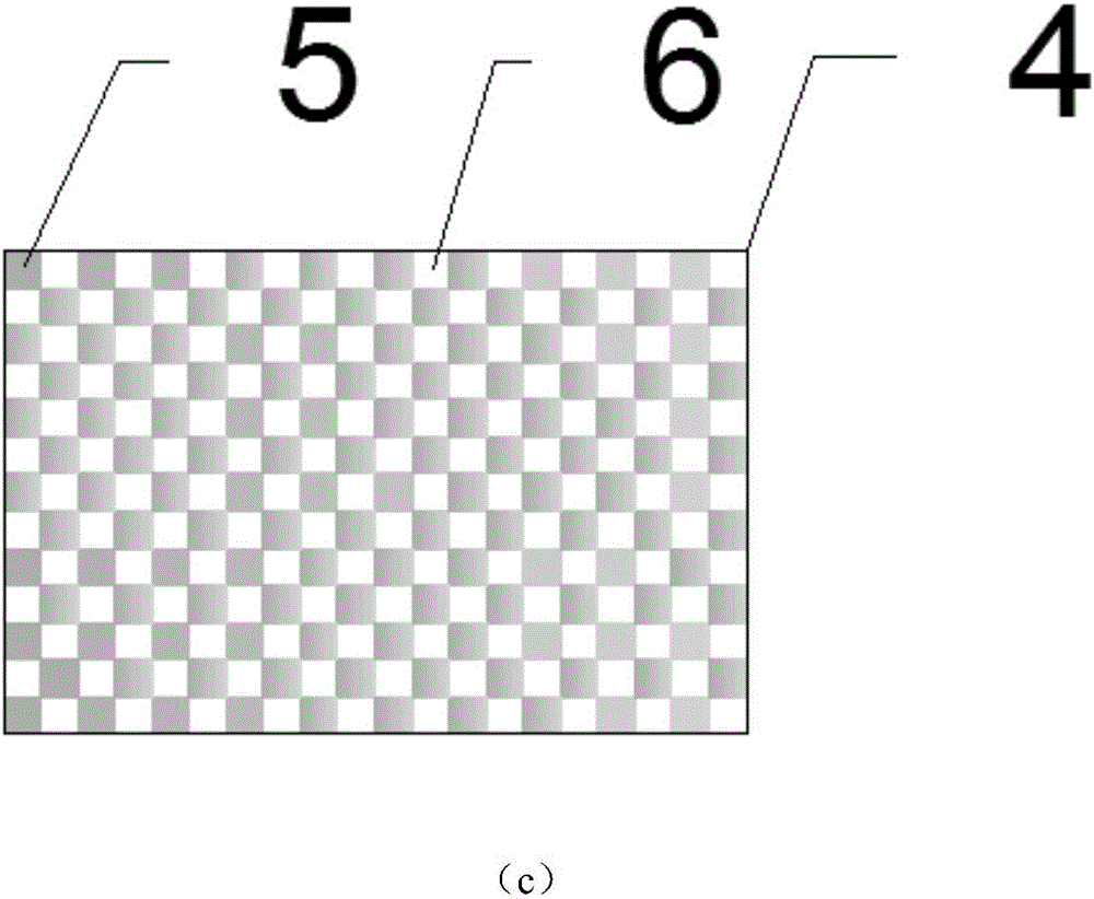
[0027] A grid-shaped energetic thin film ignition bridge, comprising an alumina ceramic substrate, a copper electrode positioned on the alumina ceramic substrate and a platinum ignition bridge region, and an energetic thin film layer positioned on the platinum ignition bridge region, said The energetic thin film layer is Al / PTFE, and the thickness of the energetic thin film layer is 2 μm. The energetic thin film layer has a grid-like structure, and the shape of a single grid is square, with a side length of 100 nanometers.

[0028] The preparation method of the above-mentioned grid-like energetic thin film ignition bridge comprises the following steps:

[0029] Step 1. Cleaning of the substrate: select an alumina ceramic substrate with a size of 3 inches as the base of the ignition bridge; ultrasonically clean the alumina ceramic substrate in acetone, alcohol, and deionized water for 10 minutes, and dry;

[0030] Step 2. Electrode preparation: put the cleaned and dried substra...


PUM


Abstract

The invention discloses an ignition bridge with a lattice-shaped energy-containing thin film, and belongs to the field of basic components for initiating explosive devices. The ignition bridge comprises a substrate, an electrode, an ignition bridge area and an energy-containing thin film layer, wherein the electrode and the ignition bridge area are located on the substrate, and the energy-containing thin film layer is located on the ignition bridge area. The ignition bridge with the lattice-shaped energy-containing thin film is characterized in that the energy-containing thin film layer is of a lattice-shaped structure; a single grid of lattice is filled with an energy-containing material A or an energy-containing material B; further, the grid filled with the energy-containing material A is only in contact with the grid filled with the energy-containing material B; the grid filled with the energy-containing material B is only in contact with the grid filled with the energy-containing material A; each contact surface between the energy-containing material A and the energy-containing material B is perpendicular to the substrate. According to the ignition bridge with the lattice-shaped energy-containing thin film, through changing a contact form between energy-containing materials, heat energy needed for ignition is effectively improved by sufficiently utilizing chemical energy from a reaction of the energy-containing thin film; the utilization rate and the conversion efficiency of energy are improved; the reliability and the stability of the ignition are guaranteed.

Description

technical field [0001] The invention belongs to the field of basic components of pyrotechnics, in particular to a bridge igniter based on a grid-shaped energetic film and a manufacturing method thereof. Background technique [0002] Pyrotechnics are one of the initial energy sources commonly used for the combustion and explosion of energetic materials. They are widely used in the fields of weaponry and national economy, such as mine blasting, safety protection airbags, micro-satellite propulsion systems, missile ignition systems, and rocket engine ignition. system etc. Bridge pyrotechnics are the most widely used pyrotechnics. It relies on electric current passing through a fine metal bridge wire with a certain resistance. The electric energy generates heat, which makes the bridge wire heat up to a scorching state, and heats the explosives around the bridge wire to make it explode. [0003] With the development of MEMS process technology, thin film ignition bridge has attra...

Claims


Application Information

Patent Timeline
IPC IPC(8): C06C5/00
CPCC06C5/00
Inventor 蒋洪川幸代鹏张宇新张万里邓新武蒋书文赵晓辉
Owner UNIV OF ELECTRONIC SCI & TECH OF CHINA
Why Eureka
Try Eureka