Vane regulation control device

A technology of regulating control and guide vane, which is applied in pump control, components of pumping devices for elastic fluids, non-variable pumps, etc., can solve deviation from design conditions, exhaust gas diffusion section and unfavorable flow in combustion chamber Influence and other issues, to achieve uniform flow field, increase efficiency, and improve the effect of outlet flow field

Active Publication Date: 2016-06-29
SHANGHAI ELECTRICGROUP CORP
View PDF7 Cites 10 Cited by
  • Summary
  • Abstract
  • Description
  • Claims
  • Application Information

AI Technical Summary

Problems solved by technology

But for the outlet guide vane, it is necessary to consider the requirements of the combustion chamber and the exhaust diffuser section on the outlet airflow angle of the guide vane. If the outlet guide vane rotates as a whole, when the adjustment amount is too large, the outlet airflow angle of the guide vane will decrease. A large deviation from the design condition will adversely affect the flow of the exhaust diffuser and the combustion chamber. Therefore, it is best to design a segmented outlet guide vane, which can adjust the front section of the outlet guide vane and fix the rear section.

Method used


Image

  • Vane regulation control device
  • Vane regulation control device
  • Vane regulation control device

Examples


Embodiment 1

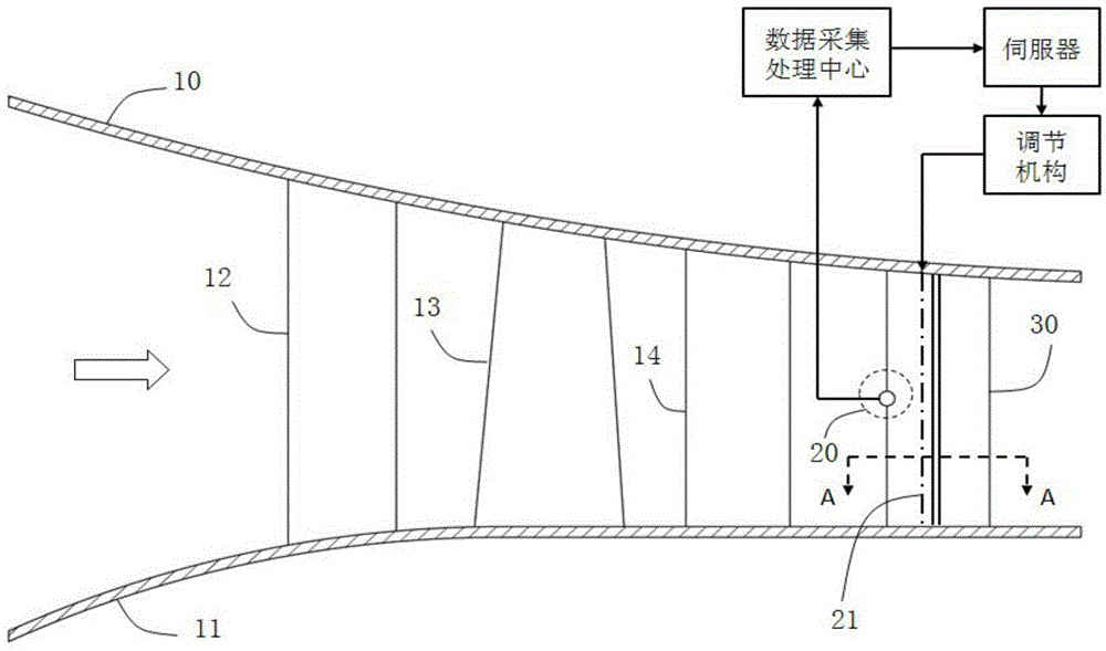
[0041] see Figure 1 to Figure 3 , the present invention discloses a guide vane adjustment control device (which can be used as a part of the compressor), including a cylinder 10, a hub 11, a moving vane 13, a stationary vane 14, an inlet guide vane 12, a variable geometry outlet guide vane 30, a guide vane Adjust the control system.

[0042] figure 1 A schematic diagram of the meridional flow of a compressor is shown, and the flow of the compressor is composed of moving blades 13, stationary blades 14, cylinders 10, and hubs 11. The gas flows through the inlet guide vane 12, pre-swirls to the rotor blade 13 at the outlet of the inlet guide vane 12, and then is compressed into a high-pressure gas in the rotor blade 13 and stationary vane 14, and the temperature also rises accordingly. Compressed air flows in the channel between the hub 11 and the cylinder 10; the rotor blade 13 is installed on the hub 11, the stationary vane 14 is installed on the cylinder 10, and the air fl...

Embodiment 2

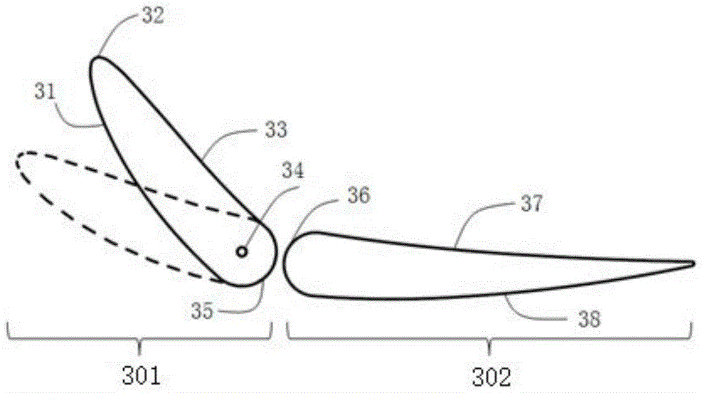
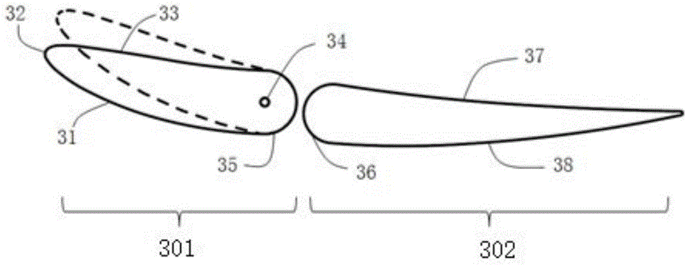
[0054] In order to prevent the compressor from stalling or clogging when it operates under variable working conditions, and considering the requirements of the combustion chamber and the exhaust diffuser section on the airflow angle at the outlet of the guide vane, the outlet is designed to be adjusted in sections, the front section is adjustable, and the rear section is fixed. It can not only ensure that the inlet angle of attack will not be too large under non-design working conditions, but also avoid the adverse effect of the change of the outlet airflow angle on the flow of the exhaust diffusion section.

[0055] In this embodiment, the variable geometry outlet guide vane includes an adjustable inlet section and a fixed outlet section, and there is a gap between the trailing edge of the adjustable inlet section and the front edge of the fixed outlet section; the gap should not be too large or too small. The gap is composed of two sections of smooth curves, through which the...


PUM


Abstract

The invention discloses a vane regulation control device. The vane regulation control device comprises a variable geometric outlet vane and a corresponding data acquisition and processing system, wherein the outlet vane comprises an inlet adjustable section and an outlet fixed section, and a clearance is arranged between the tail edge of the inlet adjustable section and the front edge of the outlet fixed section; and the clearance consists of two sections of smooth curved lines, and a pressure surface communicates with a force absorption surface through the clearance. By utilizing pressure difference between the pressure surface and the force absorption surface, a small part of air is led into a convex surface from a concave surface through a seam so as to blow a boundary layer thin. Losses are reduced, and airflow turning angle is increased. According to the vane regulation control device provided by the invention, a regulation command is sent out by the data acquisition and processing system, the mounting angle of the front part of the outlet vane is adjusted in a stepping manner, and flow separation or blockage caused by too-large attach angle of a vane inlet when the vane runs under variable work conditions is avoided; and at the same time, as the rear of the vane is kept still, the rotating of the vane produces little influence on the flow of an exhaust diffusion section and a combustion chamber.

Description

technical field [0001] The invention belongs to the technical field of impeller machinery equipment, and relates to a compressor, in particular to a guide vane adjustment control device. Background technique [0002] When the compressor operates under the design conditions, the fluid can be better attached to the airfoil, and no large separation will occur. However, when the compressor is running at a small flow rate, the inlet of the guide vane will have a large positive angle of attack, and the airflow will separate at the back arc of the blade shape. The separation zone will develop rapidly and severely with the increase of the angle of attack, eventually leading to the flow of the compressor. Stall; when the compressor is running at a large flow rate, a large negative angle of attack will appear at the inlet of the guide vane. When the negative angle of attack reaches a certain level, it will easily cause blockage of the blade passage and reduce the flow capacity of the ...

Claims


Application Information

Patent Timeline
Patent Type & Authority Applications(China)
IPC IPC(8): F04D27/00F04D29/40
Inventor 徐强何磊赵连会
Owner SHANGHAI ELECTRICGROUP CORP
Why Eureka
Try Eureka