Multi-channel harmful gas detection device and method based on micro-fluidic chip

A microfluidic chip and harmful gas technology, applied in the direction of measuring devices, material analysis by optical means, and analysis by making materials undergo chemical reactions, can solve problems such as error, difference detection, and inconvenient light absorption detection, etc., to achieve Increased flow rate, simple operation, and increased reaction area

Inactive Publication Date: 2016-06-29
JIANGSU UNIV
View PDF6 Cites 11 Cited by
  • Summary
  • Abstract
  • Description
  • Claims
  • Application Information

AI Technical Summary

Problems solved by technology

Chinese Patent No. 201320247394.1 discloses a self-flowing formaldehyde detection device based on a microfluidic chip, using a Z-shaped micro flow cell, including two inlets and one outlet, and the two inlets are respectively inlets for absorbing liquid containing formaldehyde and chromogen injection port, each inlet is equipped with a solution pool perpendicular to the surface of the microfluidic chip, and the outlet connects a thin tube with an inner diameter of 1mm to the inlet of the Z-shaped microflow cell, combining microfluidic chip technology with optical detection technology However, the defects of this device are: 1. Lack of automatic sample pretreatment and sample injection, which will not only bring tedious sample pretreatment process to the detection, but also cause detection errors due to differences in manual operations; 2. Although the Z-shaped channel described in the device also increases the reaction area, in the absorbance detection, the entire reaction color area becomes a rectangular area, which is not convenient for uniform and efficient use of the light signal emitted by the light source for absorbance detection; 3. The device can only detect formaldehyde, a harmful gas, and the actual utilization efficiency is not high

Method used


Image

  • Multi-channel harmful gas detection device and method based on micro-fluidic chip
  • Multi-channel harmful gas detection device and method based on micro-fluidic chip
  • Multi-channel harmful gas detection device and method based on micro-fluidic chip

Examples


Embodiment Construction

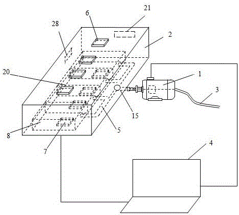
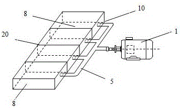
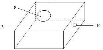
[0033] see figure 1 In the present invention, a multi-channel harmful gas rapid detection device based on a microfluidic chip has a microfluidic chip 20 , a micro pump 1 and a cartridge 2 . The micro air pump 1 is placed in the cavity of the cassette 2, and the micro air pump 1 is arranged outside the cassette 2. One end of the miniature air pump 1 passes through the through hole 15 that is opened on the side wall of the cassette 2 and then connects the collection channel 5 in the cassette 2. A rubber device is installed at the through hole 15 to prevent air leakage. The collection channel 5 is located in the cassette 2. The micro air pump 1 is connected to the microfluidic chip 20 through the collection channel 5 , and pumps gas into the microfluidic chip 20 . There is a flow meter in the micro air pump 1, which is used to measure the volume of gas sucked by the micro air pump 1. The other end of the micro air pump 1 is connected with the waste liquid channel 3 through a ru...


PUM


Abstract

The invention discloses a multi-channel harmful gas detection device and method based on a micro-fluidic chip. The micro-fluidic chip is composed of two or more same single chips bound together into a column. The interior of each single chip is provided with a liquid storage tank, a barrier liquid mixing channel and a wheel-disc-shaped gas-liquid mixing channel, wherein the liquid storage tank is connected with the wheel-disc-shaped gas-liquid mixing channel through the barrier liquid mixing channel, and the wheel-disc-shaped gas-liquid mixing channel is connected with a gas-liquid outlet through a rising channel. Multiple light-emitting diodes, multiple light-sensitive diodes and a circuit chip are further arranged. The light-sensitive diodes transmit collected data to a computer, the volume of reaction harmful gas is obtained, a flow meter transmits the volume of gas pumped by a miniature gas pump to the computer, and the percentage of the harmful gas in air is obtained by dividing the volume of the harmful gas by the volume of the gas pumped by the miniature gas pump. The micro-fluidic chip technology and the optical detection technology are combined, the automatic sample pretreatment function is achieved, and the whole detection process is fully automatic.

Description

technical field [0001] The invention relates to harmful gas detection technology and microfluidic control technology, in particular to a harmful gas rapid detection device based on a microfluidic chip. Background technique [0002] Various harmful gases in the air today are endangering people's health, such as ammonia, nitrous acid, carbon monoxide gas, etc. in greenhouses in agriculture; in people's lives, harmful gases in new house decoration and new furniture Formaldehyde, toluene, etc. At present, it is very inconvenient to detect harmful gases in the air. There are separate instruments for detecting formaldehyde. The reaction time of this instrument is very long, and only one harmful gas, formaldehyde, can be detected at a time, and the results are not accurate. [0003] Microfluidic chips have the advantages of small size, rapid response, precision and minimal consumption of reagents. Chinese Patent No. 201320247394.1 discloses a self-flowing formaldehyde detection d...

Claims


Application Information

Patent Timeline
Patent Type & Authority Applications(China)
IPC IPC(8): G01N21/78
CPCG01N21/783
Inventor 杨宁陶欣怡毛罕平周晓迪张猛
Owner JIANGSU UNIV
Why Eureka
Try Eureka