Aircraft camera shooting positioning system

A positioning system and aircraft technology, applied in the field of aircraft control, can solve problems such as being susceptible to interference, prone to operating errors, complex radio navigation equipment, etc., to achieve the effect of improving probability and solving electromagnetic shielding problems

Active Publication Date: 2016-07-06
CSSC SYST ENG RES INST
View PDF8 Cites 18 Cited by
  • Summary
  • Abstract
  • Description
  • Claims
  • Application Information

AI Technical Summary

Problems solved by technology

[0006] However, there are many shortcomings in the above-mentioned technology: 1. The radio navigation equipment is complex and susceptible to interference; 2. Artificial visual control is insufficient in anti-cloudy, rainy, foggy and inclement weather, and it is pro

Method used


Image

  • Aircraft camera shooting positioning system
  • Aircraft camera shooting positioning system
  • Aircraft camera shooting positioning system

Examples


Embodiment Construction

[0038] The preferred embodiments of the present invention will be described in detail below with reference to the accompanying drawings, where the accompanying drawings constitute a part of the application and are used together with the embodiments of the present invention to explain the principle of the present invention.

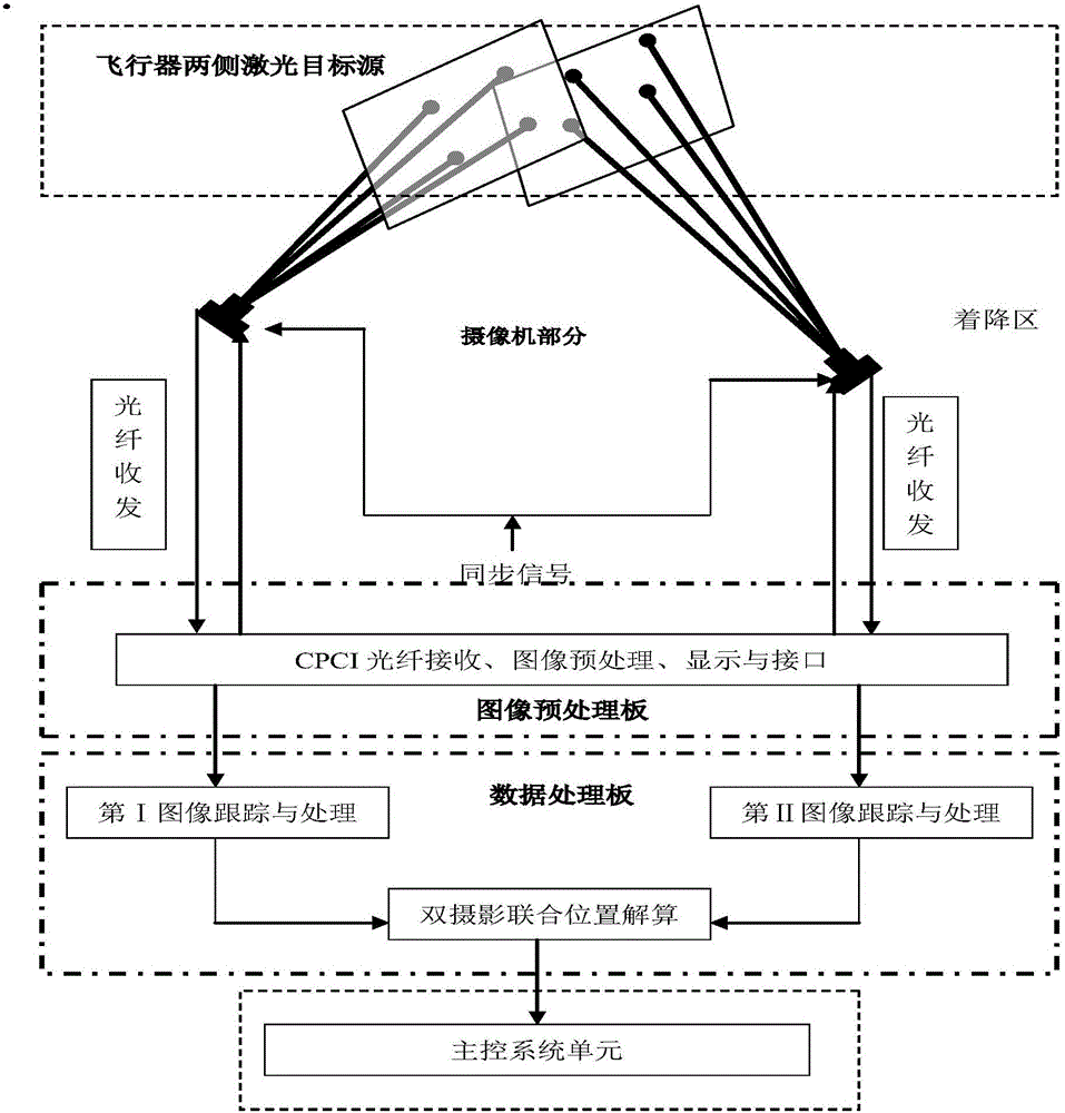
[0039] Such as figure 1 As shown, an aircraft camera positioning system includes:

[0040] Laser target source, camera, image processing unit and main control system unit and other modules, among which,

[0041] The number of said laser target sources is eight, which are installed on both sides of the aircraft's fuselage, four on each side, in an approximate convex quadrilateral shape; it provides a coordinated target for the aircraft's high-speed precise positioning system to obtain the aircraft's air position and attitude information. It is convenient to use convex quadrilateral geometric relationship algorithm to identify the corresponding target source image ...


PUM


Abstract

The invention relates to an aircraft camera shooting positioning system which comprises laser target sources, two near-infrared wide-angled cameras, an image processing unit and a master control system unit. Each of the two sides of an aircraft body of the aircraft is provided with four laser target sources, and every four laser target sources are arranged in a convex quadrilateral shape approximately; the two near-infrared wide-angled cameras are symmetrically arranged on the left side and the right side of a landing platform in the landing direction of the aircraft; the image processing unit is used for conducting target searching, capturing, recognizing and tracking on images to finish tracking measurement of the laser target sources, the position and the posture of the aircraft are calculated in real time, and calculation results are sent to the master control system unit through a CPCI bus interface; and the master control system unit is used for controlling the landing track of the aircraft according to the calculation results sent by the image processing unit. By the adoption of the aircraft camera shooting positioning system, the defects of an existing positioning system are overcome, and the positioning system is easy to operate, high in anti-jamming capability and capable of adapting to severe environments.

Description

Technical field [0001] The invention relates to the technical field of aircraft control, in particular to an aircraft camera positioning system. Background technique [0002] Currently, aircraft landing positioning systems mainly include the following forms: [0003] The microwave landing system obtains guidance data from on-board equipment. Its advantages are: the system has high accuracy and can meet the requirements of all-weather work; it allows the aircraft to choose the airport route arbitrarily and is suitable for various types of aircraft for various take-offs and landings; the system has a large capacity and can meet the requirements of the air The requirement of increased traffic volume; the equipment is small in size, and the requirement on the site is low. But it is susceptible to electronic interference. [0004] Visual guidance system, a full-time instructor uses signal flags or radio commands on the landing platform to visually guide the aircraft to land on the ship....

Claims


Application Information

Patent Timeline
IPC IPC(8): B64D45/08
CPCB64D45/08
Inventor 蔡斌许涛张鋆高斌
Owner CSSC SYST ENG RES INST
Why Eureka
Try Eureka