Intensive cooling control method for hot continuous rolling strip steel

A technology of cooling control and hot continuous rolling, applied in the direction of heat treatment process control, manufacturing tools, heat treatment equipment, etc., to avoid influence and improve strength

Active Publication Date: 2016-07-06
SHANGHAI MEISHAN IRON & STEEL CO LTD
View PDF10 Cites 7 Cited by
  • Summary
  • Abstract
  • Description
  • Claims
  • Application Information

AI Technical Summary

Problems solved by technology

[0007] The purpose of the present invention is to provide a method for intensive cooling control of hot continuous rolling strip steel, which mainly solves the technical problems of the prior art in the prior art of hot continuous rolli

Method used


Image

  • Intensive cooling control method for hot continuous rolling strip steel
  • Intensive cooling control method for hot continuous rolling strip steel
  • Intensive cooling control method for hot continuous rolling strip steel

Examples


Example Embodiment

[0030] Example 1

[0031] A 800MP grade steel for construction machinery, its chemical composition is shown in Table 1.

[0032] Table 1800MP grade engineering machinery steel chemical composition (% by weight),

[0033] The balance is Fe and unavoidable impurities.

[0034]

[0035] After the continuous casting billet is heated by the walking beam reheating furnace, it is respectively rolled into 4.0mm and 8.0mm thick steel plates by hot continuous rolling. The final rolling temperature, rolling speed, coiling temperature and cooling rate of different thickness strips are shown in Table 2.

[0036] Table 2 Hot rolling and finishing rolling process control parameters

[0037]

[0038] The cooling header is put into use as shown in Table 3.

[0039] Table 3 Cooling header commissioning table

[0040]

[0041] The mechanical properties of the hot-rolled steel sheets produced by the intensive cooling control method of the present invention and the conventional laminar cooling method are show...

Example Embodiment

[0048] Example 2

[0049] The composition of Q235 steel is upgraded to roll Q345 steel. The chemical composition of Q235 steel is shown in Table 6.

[0050] Table 6 The chemical composition of Q235 steel (% by weight), the balance is Fe and unavoidable impurities.

[0051]

[0052] The heating temperature of Q235 steel billet is 1200℃, the finishing rolling temperature is set to 810℃, and the coiling temperature is 500℃. After hot continuous rolling, 6.8mm thick steel plate is produced. The cooling header is put into use as shown in Table 7.

[0053] Table 7 Cooling header commissioning table

[0054]

[0055] After Q235 steel is upgraded and rolled by the method of the present invention, the mechanical properties of the hot-rolled steel sheet obtained are shown in Table 8.

[0056] Table 8 Mechanical properties of hot-rolled steel plates obtained after upgrading and rolling of Q235 steel by the method of the present invention

[0057]

[0058] After Q235 steel is upgraded and rolled by t...


PUM


Abstract

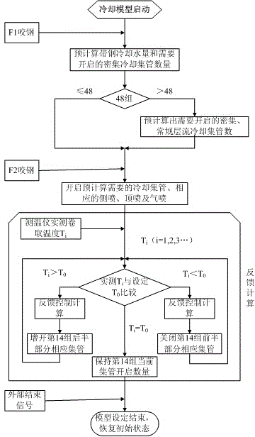
The invention relates to an intensive cooling control method for hot continuous rolling strip steel. According to the intensive cooling control method, in the prior art, hot continuous rolling strip steel laminar flow intensive cooling stable control and usage are mainly achieved. According to the intensive cooling control method for the hot continuous rolling strip steel, on a rolling line, cooling equipment is located on the rear sides of finishing mills and the front side of a recoiling machine and comprises an intensive cooling section, a conventional laminar flow cooling section and an accurate adjustment section which comprise 15 sets of manifolds totally. The intensive cooling control method comprises the following implementation steps that after steel occluding of a rack of the finishing mill F1, the water volume needed by strip steel cooling and the number of the intensive cooling manifolds needing to be opened are pre-calculated through a cooling module; during steel occluding of a rack of the finishing mill F2, a production control system controls to start the cooling module to pre-calculate the intensive cooling manifolds needing to be opened and the eight manifolds of the front half part of the fourteenth set of the accurate adjustment section; and according to a feedback control calculation result of the cooling module, the hot continuous rolling mill production control system conducts feedback control. The intensive cooling control method can be used for hot continuous rolling strip steel production in engineering machinery, general structural steel, automobile structural steel, pipeline steel and other fields.

Description

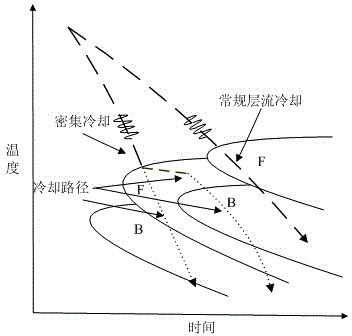
technical field [0001] The invention belongs to the technical field of iron and steel metallurgy, and relates to the laminar flow cooling technology of hot continuous rolling strip steel, in particular to a method for controlling the intensive cooling of hot continuous rolling strip steel. A method of intensive cooling control. Background technique [0002] The controlled rolling and controlled cooling process is to carry out large deformation below the recrystallization temperature to achieve the refinement and work hardening of austenite grains. After rolling, laminar cooling is used to obtain a fine-grained structure. The ultra-fast cooling process adopts a faster cooling rate than conventional laminar flow cooling, so that the steel passes through the austenite zone quickly, maintains the austenite hardening state, and cools to the phase transition temperature, so that the material has little or no damage to the toughness. Under the premise, improve the strength of the ...

Claims


Application Information

Patent Timeline
IPC IPC(8): C21D8/02C21D11/00
Inventor 段争涛卞皓孙明军
Owner SHANGHAI MEISHAN IRON & STEEL CO LTD
Why Eureka
Try Eureka