
Cooling device for transmission fluid of automotive hydraulic retarder

A hydraulic retarder and cooling device technology, applied in the direction of liquid resistance brakes, slack adjusters, brake types, etc., can solve the problem of affecting braking performance, reliability of driving brakes, energy consumption of engine cooling system, and insufficient waste heat. Utilize and other problems to achieve stable braking performance, reduce energy consumption, and increase heat transfer effects

Inactive Publication Date: 2016-07-06
WUHAN UNIV OF TECH
View PDF6 Cites 7 Cited by
  • Summary
  • Abstract
  • Description
  • Claims
  • Application Information

AI Technical Summary

Problems solved by technology

This cooling method will be affected by the performance of the heat exchanger and the current cooling power of the vehicle, which will easily make the temperature of the working oil higher, thus affecting its braking performance and service braking reliability.
At the same time, the waste heat generated by auxiliary braking is not fully utilized, and the engine cooling system consumes more energy, resulting in energy waste

Method used


Image

  • Cooling device for transmission fluid of automotive hydraulic retarder
  • Cooling device for transmission fluid of automotive hydraulic retarder

Examples


Embodiment Construction

[0022] In order to make the object, technical solution and advantages of the present invention clearer, the present invention will be further described in detail below in conjunction with the accompanying drawings and embodiments. It should be understood that the specific embodiments described here are only used to explain the present invention, not to limit the present invention.

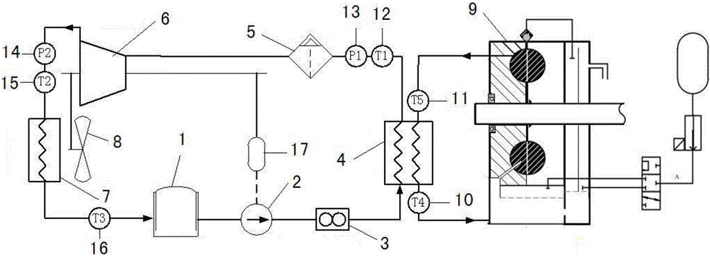
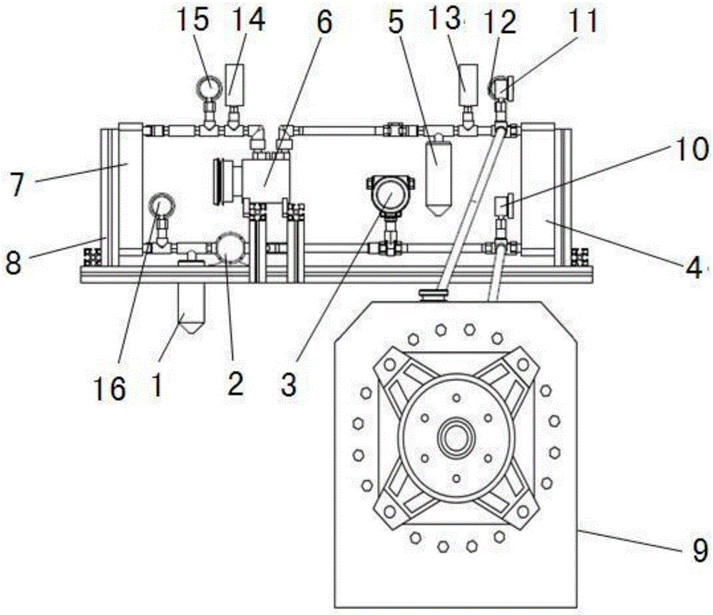
[0023] see figure 1 , figure 2 , a transmission fluid cooling device for a hydraulic retarder for a vehicle, comprising an evaporator 4, the first inlet of the evaporator 4 is connected to the oil outlet of the working chamber of the hydraulic retarder 9, and the first outlet of the evaporator 4 It is connected with the oil inlet of the working chamber of the hydraulic retarder 9, and the working oil (transmission fluid) is used as the heat source, and the working oil flows out from the oil outlet of the hydraulic retarder 9 into the first inlet of the evaporator 4, and passes through After the ...


PUM


Abstract

The invention discloses a transmission fluid cooling device for a hydraulic retarder for a vehicle, which comprises an evaporator, and the evaporator and the working chamber of the hydraulic retarder form a heat source circuit; the second outlet of the evaporator is sequentially connected with an expander and a condenser , the liquid storage tank, the working medium pump, and the second inlet of the evaporator are connected to form a Rankine circuit; the expander is connected with the power generation energy storage device and the working medium pump in turn; the expander is connected with the cooling fan, and the cooling fan is installed with the condenser Together; at the first inlet and outlet of the evaporator, a temperature sensor is provided between the condenser and the liquid storage tank, between the condenser and the expander, and between the expander and the evaporator in turn Temperature sensor, pressure sensor; a flow meter is installed at the outlet of the working fluid pump; the temperature sensor, pressure sensor, and flow meter transmit signals to the ECU, and the ECU controls the working fluid pump. The invention can efficiently utilize the waste heat of the hydraulic retarder, improve the cooling effect, make the braking of the vehicle more reliable, and ensure the driving safety.

Description

technical field [0001] The invention relates to the technical field of retarder cooling, in particular to a vehicle hydraulic retarder transmission fluid cooling device. Background technique [0002] The hydraulic retarder is a derivative type of the hydraulic coupling. When retarding the brake, the control system pumps the medium (oil) in the oil tank into the working chamber between the stator and the rotor, and the oil produces resistance to the rotor. , so that the speed of the drive shaft slows down, resulting in a retarding effect. It relies on the impact of the liquid circulation in the working wheel cavity on the blades of the fixed wheel to convert the kinetic energy of the vehicle into liquid heat energy, and then dissipates the heat energy through a certain cooling and heat dissipation method, so as to realize the deceleration and braking of the vehicle, that is, the hydraulic retarder passes through The kinetic energy of the vehicle is converted into the heat en...

Claims


Application Information

Patent Timeline
IPC IPC(8): F16D57/00F16D65/78
CPCF16D57/00F16D65/78
Inventor 谭罡风詹若冰高新王铁韩孟佐任彦君张志威卢诗晨过学迅
Owner WUHAN UNIV OF TECH
Learn More