Infrared dual-light shooting system for unmanned aerial vehicle

A shooting system and infrared shooting technology, which is applied in the parts of TV systems, TVs, color TVs, etc. Real-time switching between visible light and infrared images to achieve the effect of reducing interference and improving accuracy

Inactive Publication Date: 2016-07-13
GUANGDONG POWER FLY AIR TECH DEV CO LTD
View PDF8 Cites 13 Cited by
  • Summary
  • Abstract
  • Description
  • Claims
  • Application Information

AI Technical Summary

Problems solved by technology

[0004] Chinese patent application CN201420674359.2 discloses "A Line Patrol UAV with Infrared Thermal Imaging and Aerial Photography Functions". Rapid detection of fault points can greatly improve line inspection efficiency and reduce risks, but the infrared thermal imaging equipment carried by the UAV cannot realize fast switching between normal photography and infrared imaging
Chinese patent application CN201420139613.9 discloses "a small four-rotor UAV power line infrared inspection system", which combines a microcontroller with a high-performance thermal infrared imager TAU-640 sensor, As an effective supplementary means of visible light load, the thermal infrared camera is mounted on the UAV for the thermal infrared video image acquisition of the target area and transmitted to the ground control station through the video image transmission equipment, but this system cannot achieve the integration of visible light and infrared Combine two into one to take pictures or record videos at the same time, and it is impossible to switch between visible light and infrared images in real time

Method used


Image

  • Infrared dual-light shooting system for unmanned aerial vehicle

Examples


Embodiment

[0044] Embodiment: An infrared dual-light photography system for drones.

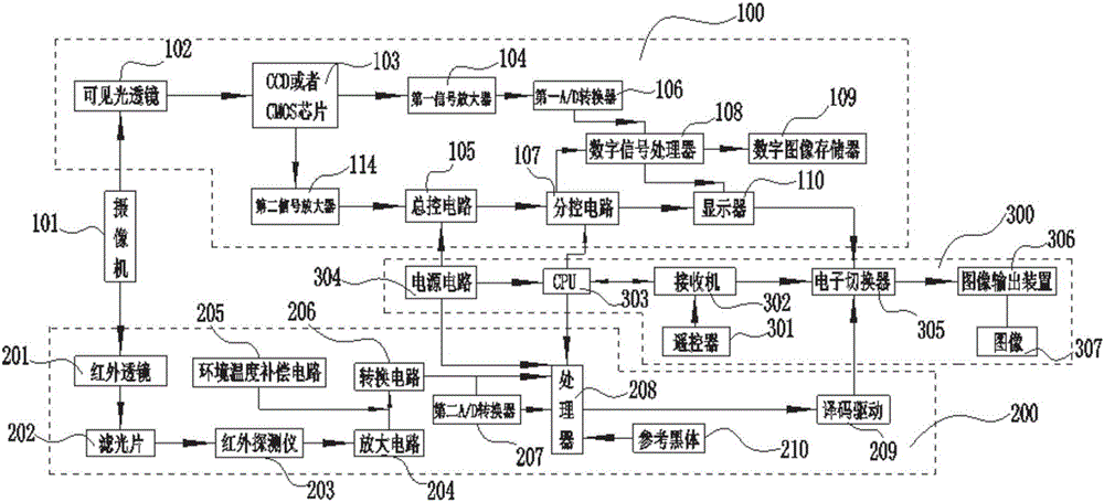
[0045] refer to figure 1 As shown, an infrared dual-light photographing system for drones includes a visible light photographing system 100, an infrared photographing system 200 and a remote control switching system 300;

[0046] The visible light photographing system 100 includes,

[0047] a camera 101 for capturing images;

[0048] the visible light lens 102 mounted on the camera 101;

[0049] a CCD or CMOS chip 103 connected to the signal output end of the visible light lens 102, the CCD or CMOS chip 103 is used to convert the optical signals collected in the visible light lens 102 into electrical signals;

[0050] a first signal amplifier 104 connected to the signal output end of the CCD or CMOS chip 103, the first signal amplifier 104 is used to amplify the electrical signal converted by the CCD or CMOS chip 103;

[0051] a first A / D converter 106 connected to the signal output end of the first...


PUM


Abstract

The invention provides an infrared dual-light shooting system for an unmanned aerial vehicle.The infrared dual-light shooting system comprises a visible light shooting system, an infrared shooting system and a remote control switching system.The visible light shooting system comprises a camera, a visible light lens, a CCD / CMOS chip, a first signal amplifier, a first A / D converter, a digital signal processor, a digital image memory, a display, a second signal amplifier, a total control circuit and a branch control circuit.The infrared shooting system comprises an infrared lens, an optical filter, an infrared detector, an amplifying circuit, a switching circuit, a processor and a decoder driver.The remote control switching system comprises a remote controller, a receiver, an electronic switcher, a signal processing CPU, an image output device and a power circuit.By means of the infrared dual-light shooting system for the unmanned aerial vehicle, visible light and infrared light can be combined to photograph or record videos at the same time, and meanwhile real-time switching of visible light image shooting and infrared image shooting can be achieved.

Description

technical field [0001] The invention belongs to the technical field of drone photography, and particularly relates to an infrared dual-light photography system for drones. Background technique [0002] An infrared thermal imager uses an infrared detector and an optical imaging objective to receive the infrared radiation energy distribution pattern of the measured target and reflect it on the photosensitive element of the infrared detector to obtain an infrared thermal image. The distribution field corresponds; the camera uses the linear propagation properties of light and the law of refraction and reflection of light, and uses photons as the carrier to transfer the light information of the scene at a certain moment to the photosensitive material in the form of energy through the camera lens, and finally becomes a photosensitive material. visible image. When the high-voltage equipment fails ionization discharge, different infrared radiation energy will be generated according...

Claims


Application Information

Patent Timeline
Patent Type & Authority Applications(China)
IPC IPC(8): H04N5/225H04N5/232H04N5/76
CPCH04N5/76H04N23/00H04N23/55H04N23/66
Inventor 张万青蔡美文廖南江何宇徐朝朝
Owner GUANGDONG POWER FLY AIR TECH DEV CO LTD
Why Eureka
Try Eureka