Blast furnace slag thermal fracture centrifugal drying method granulation device and method

A technology for dry granulation and blast furnace slag, which is applied in the improvement of process efficiency, recycling technology and other directions, can solve the problems of high-value sensible heat contained in slag that cannot be effectively recycled, huge energy waste, and large energy consumption. , to achieve the effect of obvious water saving effect, promotion of energy saving and environmental protection, and reduction of acid gas pollutants

Inactive Publication Date: 2016-07-20
于良富 +2
View PDF6 Cites 8 Cited by
  • Summary
  • Abstract
  • Description
  • Claims
  • Application Information

AI Technical Summary

Problems solved by technology

[0004] 1. It consumes a lot of water resources. It takes about 1 ton of fresh water and 10 tons of recycled water to process 1 ton of slag;
[0005] 2. SO is accompanied by water quenching process 2 and H 2 Emission of acid gas pollutants such as S;
[0006] 3. The high-value sensible heat contained in slag cannot be effectively recycled and utilized, resulting in a huge waste of energy
[0007] 4. Whether the produced slag is further processed to produce fine powder or used as a mixture for cement production, the energy consumption required for drying of about 10% to 15% of the water is huge

Method used


Image

  • Blast furnace slag thermal fracture centrifugal drying method granulation device and method

Examples


Embodiment 1

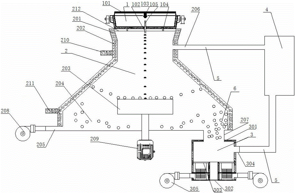
[0045] A blast furnace slag thermal breaking centrifugal dry granulation device, such as figure 1 As shown, it includes a tundish 1, a granulation chamber 2, a filled countercurrent heat exchanger 3 and a high-temperature air collection and purification device 4;

[0046] The intermediate tank 1 is a hollow body, the top of the tank is provided with a tank cover 101, the bottom of the tank is provided with a slag outlet 102, the inner wall of the tank cover 101 is provided with a heating device 103, and the inner wall of the tank is provided with a heat preservation device. Lining; several load cells 104 are provided at the bottom of the tundish, and a diversion control valve 105 is provided at the slag outlet, and the diversion control valve 105 is used to adjust the supply speed of the blast furnace slag, and the load cell 104 is used to monitor the blast furnace slag The flow rate; the heating device 103 is provided with a hole on the inner wall of the tundish cover 101, an...

Embodiment 2

[0051] A method for thermal breaking centrifugal dry granulation of blast furnace slag, utilizing the device described in Embodiment 1, comprising the following steps:

[0052] 1) centrifugal cooling

[0053] Open the slag outlet, and the liquid blast furnace slag particles with a temperature of 1450-1500°C flow from the tundish into the turntable of the granulation chamber at a flow rate of 800kg / min. The rotation speed of the turntable is 2000r / min. Under the action of centrifugal force, it flies out along the edge of the turntable, passes through the cyclone chamber and flies to the water-cooled outer cone;

[0054] In the process of flowing into the turntable and during the flight, the inflow volume is 100000Nm blasted from the granulation chamber 3 Under the action of cold wind per hour, the liquid blast furnace slag particles are in full contact with the cold wind to undergo heat exchange, and the temperature of the slag particles drops sharply. The core is still molte...

Embodiment 3

[0063] A method for thermal breaking centrifugal dry granulation of blast furnace slag, utilizing the device described in Embodiment 1, comprising the following steps:

[0064] 1) centrifugal cooling

[0065] Open the slag outlet, and the liquid blast furnace slag particles with a temperature of 1550-1600°C flow from the tundish into the turntable of the granulation chamber at a flow rate of 300kg / min. Under the action of centrifugal force, it flies out along the edge of the turntable, passes through the cyclone chamber and flies to the water-cooled outer cone;

[0066] In the process of flowing into the turntable and during the flight, the influx is 45000Nm blasted from the granulation chamber 3 Under the action of cold wind per hour, the liquid blast furnace slag particles are in full contact with the cold wind to undergo heat exchange, and the temperature of the slag particles drops sharply. The core is still molten;

[0067] When the blast furnace slag particles fly to ...


PUM

PropertyMeasurementUnit
particle diameteraaaaaaaaaa

Abstract

The invention aims at the problem existing in the prior art for blast furnace slag treatment, provides a blast furnace slag thermal fracture centrifugal drying method granulation device and method and belongs to the technical field of treating devices for blast furnace metal smelting waste. The device comprises an intermediate tank, a granulation chamber, a filling type countercurrent heat exchanger and a high-temperature air collecting purifier. The intermediate tank is located on the upper portion of the granulation chamber. The granulation chamber is located on the upper portion of the filling type countercurrent heat exchanger. The intermediate tank, the granulation chamber and the filling type countercurrent heat exchanger are sequentially connected. The high-temperature air collecting purifier is located outside and is connected with the granulation chamber and the filling type countercurrent heat exchanger through pipelines. According to the device and the method, a drying method is adopted for treating blast furnace slag, high-temperature sensible heat of the blast furnace slag can be utilized for generating power, precious water resources can be saved, emission of harmful gas is reduced, and energy consumption is reduced. Moreover, for the treated blast furnace slag, due to the extremely low water content of the dried slag, the vitrification rate can be kept 95% or above.

Description

technical field [0001] The invention belongs to the technical field of blast furnace metal smelting waste treatment, and in particular relates to a blast furnace slag thermal breaking centrifugal dry granulation device and method. Background technique [0002] Blast furnace slag is a by-product of the ironmaking process, which contains abundant sensible heat resources. For every ton of iron produced, about 0.3 tons of blast furnace slag is produced, and the slag discharge temperature is around 1450°C. According to the domestic production of 700 million tons of pig iron in 2014, the domestic annual output of blast furnace slag is about 200 million tons, and the heat contained in it is equivalent to about 12 million tons of standard coal. [0003] At present, steel mills generally adopt the "wet method" of water quenching granulation for blast furnace slag, and then use it as raw material for cement production. This "wet" process has the following problems: [0004] 1. It c...

Claims


Application Information

Patent Timeline
Patent Type & Authority Applications(China)
IPC IPC(8): C21B3/06
CPCC21B3/06Y02P10/20Y02W30/50
Inventor 于良富曹旭远林杨
Owner 于良富
Why Eureka
Try Eureka