
A free piston Stirling heat engine

A Stirling engine and heat engine technology, applied in the direction of hot gas variable displacement engine devices, mechanical equipment, engine components, etc., can solve the difficulty of increasing design, materials, and processing technology, and require high precision in design, processing, and assembly , unbalanced forces on both sides, etc., to achieve the effect of reducing design difficulty and material selection requirements, reducing process and assembly difficulty, and reducing axial stiffness

Active Publication Date: 2017-07-14
LIHAN THERMOACOUSTIC TECH SHENZHEN +1
View PDF5 Cites 0 Cited by
  • Summary
  • Abstract
  • Description
  • Claims
  • Application Information

AI Technical Summary

Problems solved by technology

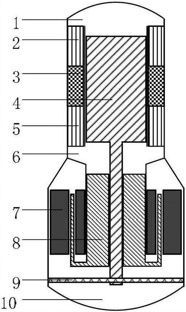
figure 1 In the structure shown, the falcon part of the ejector is coupled with the linear motor, and the power piston supporting leaf spring is placed in the back cavity of the motor. This structure reduces the design difficulty of the planar leaf spring and is easy to achieve a large diameter-to-axis stiffness ratio, but the discharge The falcon part of the device is a slender rod. Because of the gap seal between it and the power piston, it requires high precision in design, processing and assembly, and there are structural instability factors because of the unbalanced force on both sides.
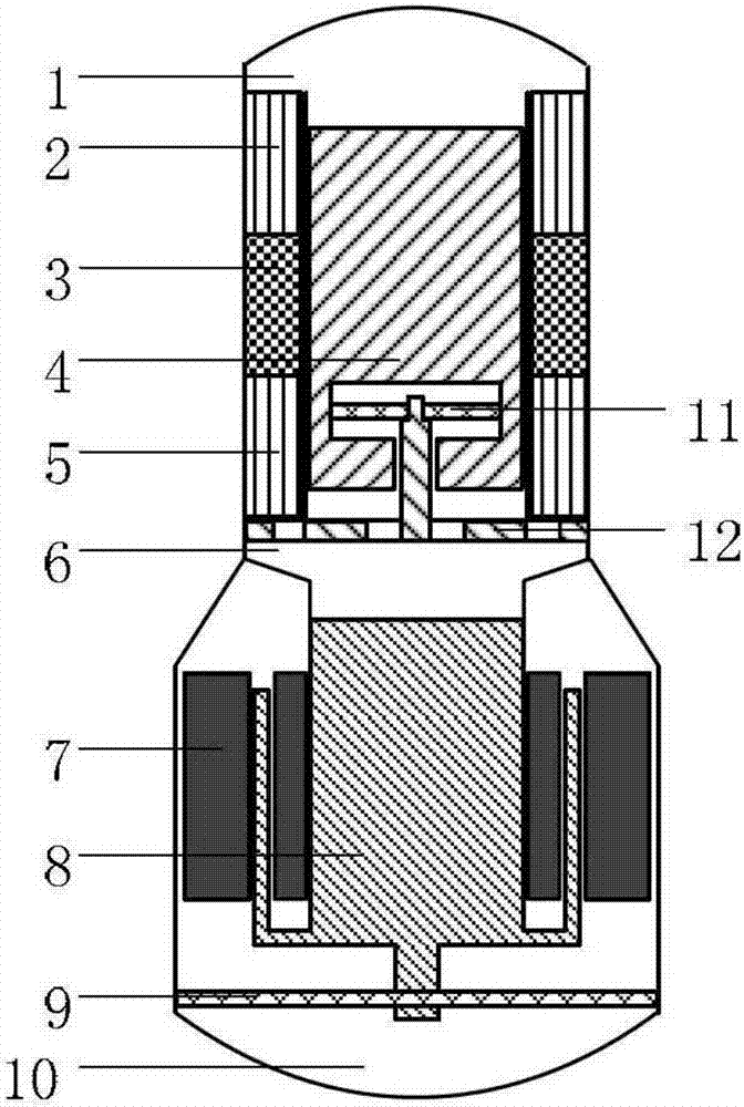
figure 2 In the structure shown, the ejector supporting leaf spring 11 is placed inside the ejector, and the falcon part of the ejector is integrated with the ejector base 12. This structure eliminates the disadvantage that the ejector's falcon part is long and easily deformed and unstable, but The size of the ejector supporting leaf spring is restricted by the size of the ejector, which significantly increases the difficulty of design, material, and processing technology, and its reliability is also affected

Method used


Image

  • A free piston Stirling heat engine
  • A free piston Stirling heat engine
  • A free piston Stirling heat engine

Examples


Embodiment 1

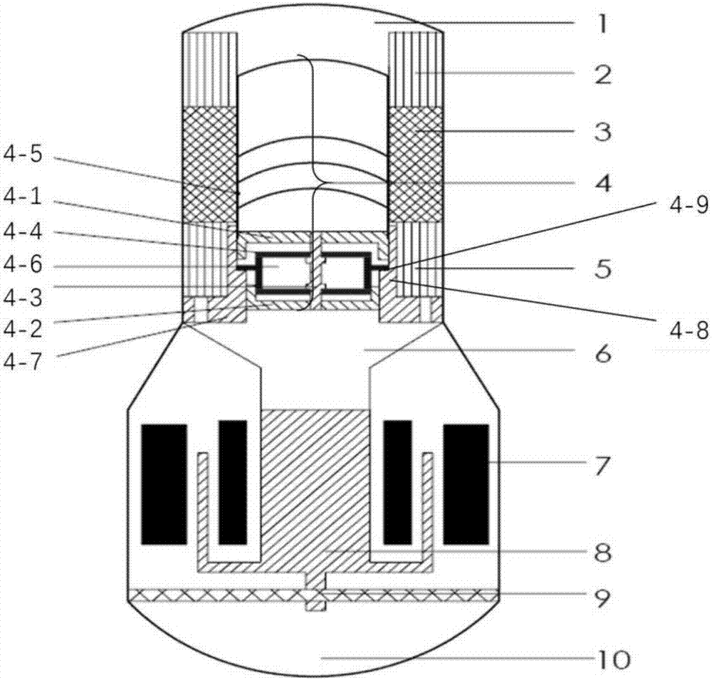
[0039] image 3 Schematic diagram of the structure of the free-piston Stirling heat engine provided by Example 1 of the present invention.

[0040] A free-piston Stirling heat engine, said Stirling heat engine comprising a Stirling engine and a linear oscillating motor, said any Stirling engine comprising a displacer 4, said displacer 4 comprising an upper plug body 4 -1. Lower plug body 4-2, falcon part 4-3, planar support leaf spring 4-4, high temperature cylinder 4-5, cavity 4-6 and base 4-7;

[0041] The base 4-7 is fixed on the bottom of the room temperature heat exchanger 5, the base 4-7 is provided with a stepped cylinder 4-8, the inner wall of the stepped cylinder 4-8 is provided with a step 4-9, and the upper part of the step 4-9 The inner wall gap seal of the stepped cylinder 4-8 is provided with an upper plug body 4-1, and the inner wall gap seal of the stepped cylinder 4-8 at the bottom of the step 4-9 is provided with a lower plug body 4-2, and the upper plug bod...

Embodiment 2

[0059] Figure 4 It is a structural schematic diagram of the free-piston Stirling heat engine of Embodiment 2 of the present invention. Depend on Figure 4 It can be seen that the free-piston Stirling heat engine of the present embodiment is composed of a free-piston Stirling engine (or refrigerator) and two linear oscillating motors; the linear oscillating motors are arranged symmetrically, and are connected with the engine (or refrigerator). tube coupling.

[0060] The working principle of embodiment 2 is the same as that of embodiment 1, the difference is that there are two linear motors in embodiment 2, and the structural parameters are exactly the same, and they are arranged symmetrically; this arrangement can make the movement phase difference of the two motor power pistons 180 degree, so as to completely offset the vibration of the casing caused by the power piston of the motor. Compared with Example 1, the vibration and noise of Example 2 are smaller.

Embodiment 3

[0062] Figure 5 A schematic diagram of the double-mounted structure of the free-piston Stirling heat engine provided by Embodiment 3 of the present invention; Figure 5 As shown, the free-piston Stirling heat engine of the present embodiment is made up of two free-piston Stirling engines (or refrigerators) and two linear oscillating motors; the motors (refrigerators) and the linear motors are symmetrically arranged respectively, and the motors and The linear motors are connected with connecting pipes.

[0063] The working principle of embodiment 3 is the same as that of embodiment 1, except that there are two engines (refrigerators) and linear motors in embodiment 3, and the structural parameters are exactly the same, and they are symmetrically arranged. This arrangement completely cancels out casing vibrations generated by the movement of the ejector and motor pistons. Compared with Examples 1 and 2, Example 3 has smaller vibration and noise and higher power density.


PUM


Abstract

The invention provides a free piston Stirling heat engine. The Stirling heat engine comprises a plurality of Stirling engines and a plurality of linear oscillation motors; and any Stirling engine comprises an exhaust device (4) and is characterized in that each exhaust device (4) comprises an upper piston body (4-1), a lower piston body (4-2), tenon parts (4-3), plane supporting plate springs (4-4), high-temperature barrels (4-5), a cavity (4-6), a base (4-7), a step type cylinder (4-8) and steps (4-9). According to the free piston Stirling heat engine, gas springs are utilized to reduce the rigidity of the plate springs, it can be guaranteed that gaps between the exhaust devices and the cylinders are sealed through the plane supporting plate springs, and design, materials and technology difficulty of the plane supporting plate springs are also reduced; a dual-piston-body structure is adopted for each exhaust device, each upper piston body and the corresponding lower piston body are assembled on the two sides of the two corresponding sets of plane supporting plate springs, the technology and assembly difficulty is reduced, reciprocating vibration of the exhaust devices is made more stable, the reliability of the system is improved, and the service life of the system is prolonged.

Description

technical field [0001] The invention relates to thermal power technology, in particular to a free-piston Stirling heat engine. Background technique [0002] Free-piston Stirling heat engine is a structural form of thermoacoustic heat engine. It uses an ejector to replace the crankshaft structure in the traditional Stirling heat engine, and adjusts the phase distribution of the sound field by controlling the dynamic mass of the ejector and the stiffness of the leaf spring to achieve efficient thermal-acoustic or acoustic-thermal conversion, and through impedance matching and sound field The coupling method realizes efficient coupling with the linear motor or linear compressor, and constructs a free-piston Stirling generator or an electric-driven free-piston Stirling refrigerator. The Stirling engine using the forward Stirling cycle absorbs heat through the high-temperature heat exchanger, releases heat through the room temperature heat exchanger, and realizes the conversion ...

Claims


Application Information

Patent Timeline
Patent Type & Authority Patents(China)
IPC IPC(8): F02G1/043F02G1/053
CPCF02G1/0435F02G1/053F02G2280/10
Inventor 余国瑶李小伟李海冰刘斌胡剑英吴张华戴巍罗二仓
Owner LIHAN THERMOACOUSTIC TECH SHENZHEN
Learn More