Numerical value calibration method for line structured light vision sensor

A visual sensor and line structured light technology, applied in the direction of instruments, optical devices, measuring devices, etc., can solve the problems of small number of calibration points, extraction error calibration accuracy, limited measurement range, etc., and achieve simple production, simple method and low cost. low effect

Active Publication Date: 2016-07-20
HEBEI UNIVERSITY OF SCIENCE AND TECHNOLOGY
View PDF4 Cites 30 Cited by
  • Summary
  • Abstract
  • Description
  • Claims
  • Application Information

AI Technical Summary

Problems solved by technology

The disadvantage of this method is that the number of calibration points obtained is small and the calibration accuracy is not high.
[0007] In order to solve the problem that the target point is difficult to coincide with the laser plane and affect the calibration accuracy, Wei Zhenzhong of Beihang University proposed a calibration method based on double cross-ratio constant line structured light sensor, which was published in the Journal of Mechanical Engineering, 2005, 41( 2): 210-214, "A Calibration Method for Line Structured Light Vision Sensor"
The disadvantage is that the high-precision three-dimensional target processing required for calibration is relatively difficult, and the influence of lens distortion on the measurement results is not considered in depth.
The disadvantage of the method is that the calibration accuracy is not very high
The disadvantages of the above method are: (1) During the calibration p...

Method used


Image

  • Numerical value calibration method for line structured light vision sensor
  • Numerical value calibration method for line structured light vision sensor
  • Numerical value calibration method for line structured light vision sensor

Examples


Embodiment Construction

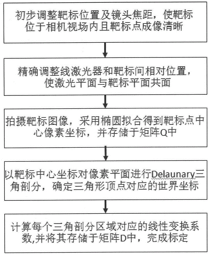
[0041] The specific implementation manners of the present invention will be further described below in conjunction with the accompanying drawings, so as to make the technical solution of the present invention easier to understand and grasp.

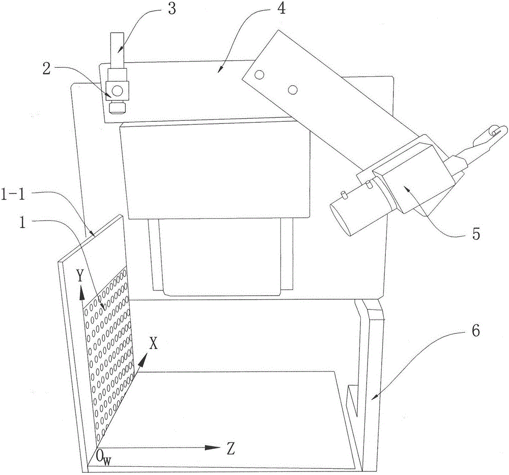
[0042] figure 1 It is a calibration diagram of a line structured light vision sensor, which is composed of a calibration target 1, a laser fixing sleeve 2, a line laser 3, a connecting frame 4 between the line laser and the camera, a camera 5, and a vertical support 6, and is characterized in that:

[0043] The calibration target 1 is placed vertically, and the target plane coincides with the laser plane emitted by the line laser 3;

[0044] In order to meet the requirement that the target plane coincides with the laser plane, the shape of the line laser 3 should be cylindrical, and can be rotated at a specific angle in the laser fixing sleeve 2; the laser fixing sleeve 2 is characterized by a Circular sleeve, its inner diameter is sligh...


PUM


Abstract

The invention discloses a numerical value calibration method for a line structured light vision sensor. The method comprises steps: an equidistantly-arranged dot array is made as a calibration target, the target position and a focal length are initially adjusted to enable the target to be completely placed in a view field of a camera, and a target point image is distinct; the relative position between a line structured laser plane and the calibration target is precisely adjusted to enable the laser plane and the target plane to be coplanar; the power supply of the laser is cut off, the focal length of the camera is adjusted precisely again, the target image photographed by the camera is ensured to be distinct, an ellipse fitting method is adopted to obtain pixel coordinates of each target point center, and the pixel coordinates are stored in a matrix Q; the target center coordinates in the matrix Q are used for carrying out Delaunary triangulation on the pixel plane, the point at the left corner of the target is marked as the original point of a world coordinate system 0WXY, and world coordinates corresponding to a vertex are determined; and a linear transformation coefficient corresponding to each triangulation area is calculated, and the linear transformation coefficient is stored in a transformation coefficient matrix D. The calibration method of the invention is simple and easy to operate, the computing efficiency is high, and the calibration precision is good.

Description

technical field [0001] The invention belongs to the field of computer vision measurement and relates to a high-precision numerical calibration method for a line structured light vision sensor. Background technique [0002] The line structured light vision sensor is a non-contact measuring device, mainly composed of a camera and a line laser. It has the advantages of simple structure, non-contact, and fast measurement speed, and is widely used in many industrial fields such as contour measurement, reverse engineering, and online monitoring. [0003] The line structured light vision sensor calculates the actual outline of the measured object by analyzing the deformed light stripes obtained by the intersection of the laser plane emitted by the line laser and the measured object. In order to establish the correspondence between the laser light stripe image and the actual contour coordinates, it is necessary to calibrate the line structured light vision sensor first. The calibr...

Claims


Application Information

Patent Timeline
IPC IPC(8): G01B11/24
CPCG01B11/24
Inventor 周京博李玥华黄风山
Owner HEBEI UNIVERSITY OF SCIENCE AND TECHNOLOGY
Why Eureka
Try Eureka