Photocatalytic ceramsite as well as preparation method and application thereof

A technology of photocatalysis and ceramsite, which is applied in the field of photocatalytic materials, can solve the problems of no discovery and less co-doping, and achieve the effects of solving difficult recycling, improving photocatalytic activity, and broadening the wavelength range of photoresponse

Active Publication Date: 2016-07-27
郑州普利飞尔环保科技有限公司
View PDF3 Cites 9 Cited by
  • Summary
  • Abstract
  • Description
  • Claims
  • Application Information

AI Technical Summary

Problems solved by technology

In recent years, the TiO 2 The doping modification of nanotubes has achieved many important results, but the modification of co-doping is less reported and a cheap loading material has not been found to combine with TiO 2 nanotube binding

Method used


Image

  • Photocatalytic ceramsite as well as preparation method and application thereof

Examples


preparation example Construction

[0047] (1) Preparation method of ceramsite carrier

[0048] (1) Get 40 parts of sludge, 40 parts of kaolin, 10 parts of sawdust, and 10 parts of calcium hydroxide, all in parts by weight. Fully mix and stir the above raw materials to make slurry, use a granulator to make the slurry into spherical particles with a diameter of 2mm, and dry it to form a billet;

[0049] (2) Place the mud body prepared in step (1) in a high-temperature sintering furnace, raise the temperature to 550°C at a heating rate of 80°C / h and keep it for 2 hours, and then continue to heat it up to 1000°C at a heating rate of 100°C / h After 3 hours, the heating was stopped, and the furnace temperature was lowered to room temperature at a rate of 150°C / h to obtain porous ceramsite for later use.

[0050] (2) Preparation method of ceramsite carrier

[0051] (1) Get 50 parts of sludge, 30 parts of bentonite, 10 parts of activated carbon, and 15 parts of calcium hydroxide, all in parts by weight. Fully mix and...

Embodiment 1

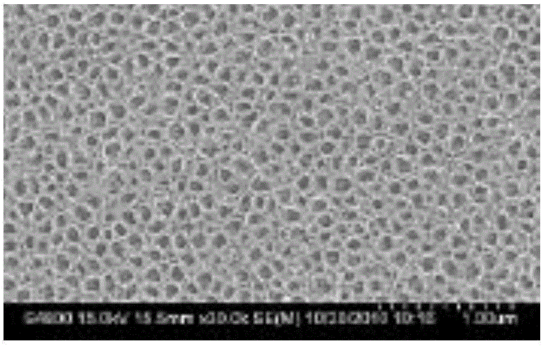
[0068] A method for preparing photocatalytic ceramsite, doping TiO with Sm in a ratio of 1:10 2 Nano-powder and porous ceramsite are placed in NaOH aqueous solution with a pH of 10. The amount of NaOH aqueous solution should be enough to cover the porous ceramsite; magnetic stirring for 10 minutes, ultrasonic oscillation for 30 minutes; after completion, pour the sample into polytetrafluoroethylene In a reaction kettle with the substrate as the substrate, react at 120°C for 24 hours, cool to room temperature under natural conditions, and after filtration, place the porous ceramsite in dilute hydrochloric acid solution for pickling, and then wash with deionized water until the porous ceramsite Neutral; put porous ceramsite in N 2 Sm, N co-doped TiO can be obtained by high-temperature calcination at 600 °C in an atmosphere furnace 2 Nanotube photocatalytic ceramsite.

[0069] Among them, Sm doped TiO 2 The nano powder is prepared by the first method, and the porous ceramsite ...

Embodiment 2

[0071] A method for preparing photocatalytic ceramsite, the preparation method of this embodiment is the same as that of embodiment 1, the only difference is: Sm doped TiO 2 The nano powder is prepared by the (second) method, and the porous ceramsite is prepared by the (second) method.


PUM

PropertyMeasurementUnit
particle diameteraaaaaaaaaa
diameteraaaaaaaaaa
diameteraaaaaaaaaa

Abstract

The invention relates to photocatalytic ceramsite as well as a preparation method and an application thereof. Firstly, the ceramsite is prepared from sludge, clay, activated carbon or wood flour, calcium hydroxide and other raw materials, Sm-doped TiO2 nanopowder is prepared with a sol-gel method, TiO2 nanotubes are prepared with a hydrothermal method, supporting of the TiO2 nanotubes and ceramsite is completed, finally, porous ceramsite is subjected to gas-phase sintering in the presence of N2, and doping modification of TiO2 nanotubes by N elements is completed. The raw materials are cheap, the process is delicate, the prepared ceramsite has uniform and adjustable sizes, the supported modified TiO2 nanotubes have moderate lengths, uniform diameters and large surface area and have high attachment force with ceramsite, the photocatalytic activity is high, and the photocatalytic ceramsite can be used for photocatalysis treatment of organic wastewater and can also be used for oxidative degradation of gas-phase organic matters.

Description

technical field [0001] The invention relates to the technical field of photocatalytic materials, in particular to a photocatalytic ceramsite, its preparation method and application, and more specifically to a photocatalytic ceramsite loaded with samarium and nitrogen co-doped titanium nanotubes, its preparation method and application. Background technique [0002] Semiconductor photocatalysis technology has developed rapidly in recent years, the backbone of which is TiO 2 why. Usually TiO 2 There are three crystal forms: anatase, rutile and brookite. In 1972, Fujishima found that titanium dioxide decomposed water into H under light conditions. 2 and O 2 After that, scientific research workers have never stopped studying titanium dioxide. As an n-type semiconductor, titanium dioxide has a wide band gap, which is 3.2 eV in the anatase crystal form and 3.0 eV in the rutile crystal form. When it is subjected to a wavelength less than or equal to 387.5 nm When irradiated by...

Claims


Application Information

Patent Timeline
Patent Type & Authority Applications(China)
IPC IPC(8): B01J27/24C02F1/32B01D53/86
CPCY02W10/37B01J35/004B01D53/8668B01J27/24C02F1/32C02F2305/10
Inventor 苏磊王永强
Owner 郑州普利飞尔环保科技有限公司
Why Eureka
Try Eureka