Method for preparing micro-nano composite structure through nanosecond laser induced cracks

A composite structure, laser-induced technology, applied in laser welding equipment, nanotechnology for materials and surface science, nanotechnology, etc., to achieve the effect of simple operation, high processing efficiency, and reduced reflectivity

Active Publication Date: 2016-07-27
XI AN JIAOTONG UNIV
View PDF8 Cites 15 Cited by
  • Summary
  • Abstract
  • Description
  • Claims
  • Application Information

AI Technical Summary

Problems solved by technology

Using traditional ablation and laser induction, it is difficult to simultaneously obtain ...

Method used


Image

  • Method for preparing micro-nano composite structure through nanosecond laser induced cracks
  • Method for preparing micro-nano composite structure through nanosecond laser induced cracks
  • Method for preparing micro-nano composite structure through nanosecond laser induced cracks

Examples


Embodiment 1

[0017] A method for preparing a micro-nano composite structure using nanosecond laser-induced cracks, comprising the following steps:

[0018] 1) Polish the surface of industrial pure titanium TA18 to a surface roughness of 100-120nm;

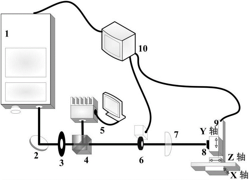
[0019] 2) Build the optical path, refer to figure 1 , the optical path includes a nanosecond laser 1, the output light of the nanosecond laser 1 passes through the mirror 2 to turn the optical path by 90°, and the reflected light passes through the aperture diaphragm 3, the beam splitting prism 4, the shutter 6, and the focusing lens 7 to irradiate vertically on the moving object On the processing station of stage 9, nanosecond laser 1, shutter 6, mobile stage 9 and computer 10 are connected, and the combination of beam splitter prism 4 and power meter 5 is used to detect the laser power. cut off, adjust the size of the light aperture through the small hole diaphragm 3, and use a focusing lens 7 with a focal length of 100 mm for focusing the o...

Embodiment 2

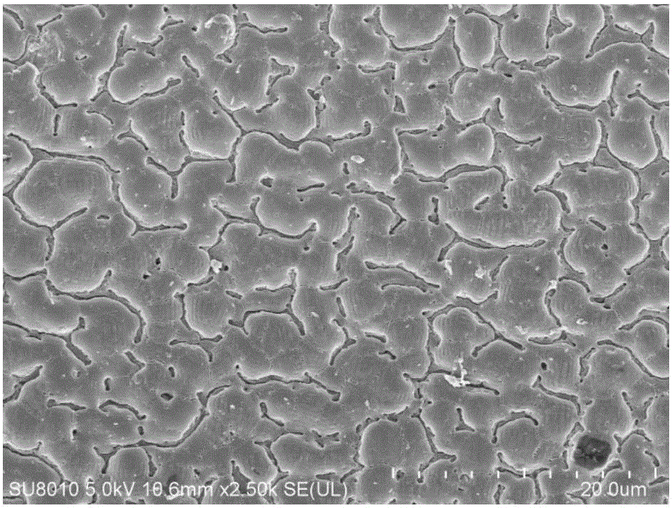
[0024] Move the mobile stage in step 4) of Example 1 along the horizontal direction, and change the speed to 0.01mm / s to obtain a surface composite structure in which microstructures below 5 μm are combined with nanostructures below 1 μm, refer to image 3 , the edges and corners of the surface of the composite structure are initially obvious.

Embodiment 3

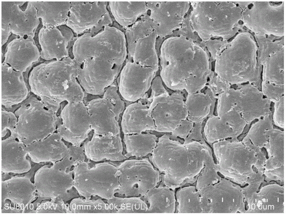
[0026] Move the mobile stage in the step 4) of Example 1 along the horizontal direction, and the speed becomes 0.004mm / s to obtain a surface composite structure in which microstructures below 5 μm are combined with nanostructures below 1 μm, refer to Figure 4 , the surface of the composite structure is angular.


PUM


Abstract

Disclosed is a method for preparing a micro-nano composite structure through nanosecond laser induced cracks. Firstly, commercial pure titanium TA1 is subjected to surface polishing; then a light path is built and comprises a nanosecond laser device; output light of the nanosecond laser device passes through a reflecting mirror to make the light path turn by 90 degrees; reflected light sequentially passes through a small hole diaphragm, a beam splitter prism, a shutter and a focusing lens to vertically irradiate on a processing station of a movable objective table; the nanosecond laser device, the shutter and the movable objective table are connected with a computer; output laser parameters of the nanosecond laser device are adjusted through the computer; and the polished commercial pure titanium is fixed to the processing station of the movable objective table and subjected to nanosecond laser irradiation, the movable objective table is controlled through the computer to move in the horizontal direction, and the surface composite structure with a micron-structure below 5 [mu]m and a nano-structure below 1 [mu]m combined is obtained. According to the method for preparing the micro-nano composite structure through the nanosecond laser induced cracks, characteristics of crack generation under the heating action of a titanium material and microstructural controllable laser propagation are utilized, the operation is simple, and the processing efficiency is high.

Description

technical field [0001] The invention belongs to the technical field of micro-nano structure preparation and laser micro-machining, and in particular relates to a method for preparing a micro-nano composite structure by using nanosecond laser-induced cracks. Background technique [0002] At present, in order to prepare micro-nano structures on the surface of materials to improve the anti-reflection and hydrophobicity of the material surface, chemical corrosion, mechanical processing, reactive ion etching and laser micro-groove etching or induced nano-ripples are used. Among them, chemical corrosion has poor controllability on the surface structure, the size of the surface structure of mechanical processing is large, and the cost of reactive ion etching is high. These shortcomings are the major reasons that limit its development. Laser processing, due to its high processing precision and small size, has been widely used in semiconductors, metals and insulating materials. Trad...

Claims


Application Information

Patent Timeline
IPC IPC(8): B23K26/00B82Y40/00B82Y30/00
CPCB82Y30/00B82Y40/00B23K26/352
Inventor 王文君潘爱飞梅雪松孙学峰崔健磊王恪典
Owner XI AN JIAOTONG UNIV
Why Eureka
Try Eureka