High repetition frequency narrow pulse laser emission circuit

A technology of laser emission and narrow pulse, which is applied in the field of laser measurement, can solve the problems of peak power drop and narrowing, and achieve the effects of simple circuit, prevention of reverse overexcitation, and constant working temperature

Inactive Publication Date: 2016-07-27
NANJING UNIV OF SCI & TECH
View PDF3 Cites 6 Cited by
  • Summary
  • Abstract
  • Description
  • Claims
  • Application Information

AI Technical Summary

Problems solved by technology

However, due to the influence of the semiconductor characteristics of the laser and the distributed inductance and distributed capacitance of the drive circuit, there is a conflicting relationship between the pulse waveform of the laser emission pulse and parameters such as repetition frequency and output power.
The relationship b

Method used


Image

  • High repetition frequency narrow pulse laser emission circuit
  • High repetition frequency narrow pulse laser emission circuit
  • High repetition frequency narrow pulse laser emission circuit

Examples


Embodiment Construction

[0016] It is easy to understand that, according to the technical solution of the present invention, those skilled in the art can imagine various implementations of the high repetition rate narrow pulse laser emitting circuit of the present invention without changing the essence of the present invention. Therefore, the following specific embodiments and drawings are only exemplary descriptions of the technical solution of the present invention, and should not be regarded as the entirety of the present invention or as a limitation or limitation on the technical solution of the present invention.

[0017] Drive circuit

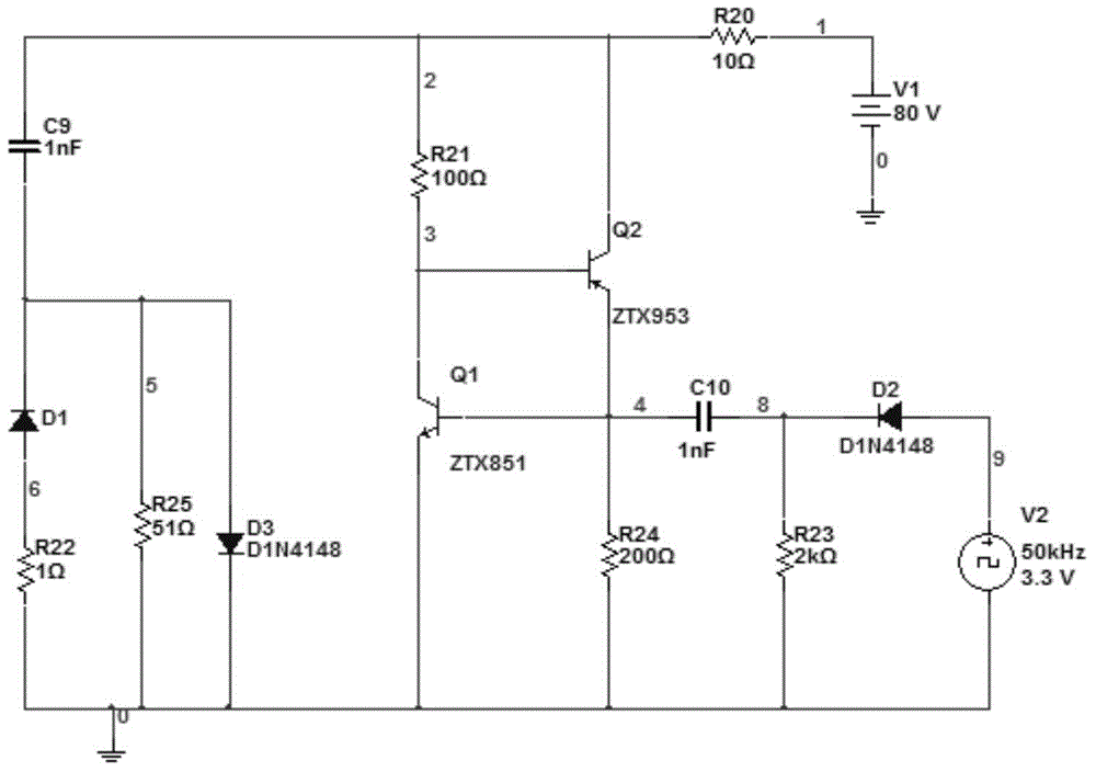
[0018] In this example, if figure 1 As shown, the driving circuit of the laser diode SPLLL90_3 includes a charging voltage source V1, a trigger signal source V2, a twentieth resistor R20, a twenty-first resistor R21, a twenty-second resistor R22, a twenty-third resistor R23, a twentieth resistor Four resistors R24, twenty-fifth resistor R25, ninth capacitor C9, ...


PUM


Abstract

The invention proposes a high repetition frequency narrow pulse laser emitting circuit. It includes a driving circuit and a temperature control circuit of the laser diode; the driving circuit includes a trigger signal source, a charging and discharging circuit and a switching circuit; the driving circuit controls the closing of the switching circuit through the triggering signal, and then controls the frequency and frequency of the laser diode emitting laser through the charging and discharging circuit. pulse width to realize high repetition frequency and narrow pulse laser emission; the temperature control circuit includes a thermoelectric cooler and a peripheral circuit based on a control chip; the thermoelectric cooler is attached to a laser diode for temperature sensing, and the obtained temperature value is input to the The peripheral circuit of the chip, the peripheral circuit realizes the cooling control of the thermoelectric cooler by controlling the chip, thereby reducing the temperature of the laser diode and making it work at a constant temperature. The invention realizes the emission of pulsed laser and effectively improves the working distance and precision of laser ranging.

Description

technical field [0001] The invention belongs to the field of laser measurement, and specifically relates to high-frequency narrow-pulse emission of pulsed lasers, which is applied to intelligent anti-collision of laser radar vehicles, urban construction and planning, laser proximity fuzes, active laser guidance, etc. Background technique [0002] Pulsed laser measurement uses a laser as a light source and a laser as a carrier. According to the time-of-flight principle, the distance is measured by detecting the time difference between the laser emission pulse and the laser echo pulse. It has the advantages of simple structure, low price, high reliability, and anti-interference It has the advantages of strong performance and no need for cooperative targets, and has been widely used in civilian and military applications. [0003] Realizing high repetition frequency and narrow pulse of laser is an important means to improve the working distance, dynamic detection accuracy and an...

Claims


Application Information

Patent Timeline
IPC IPC(8): G01S7/484
Inventor 任侃周玉蛟杨锦清唐彦琴潘佳惠孙爱娟
Owner NANJING UNIV OF SCI & TECH
Why Eureka
Try Eureka