
Synthesized pipe rack with frame composite structure

A technology of integrated pipe gallery and combined structure, applied in underwater structures, infrastructure engineering, hydraulic engineering and other directions, can solve the problems of limited bearing capacity, plate radian deformation, high processing cost, and achieve torsional stiffness and anti-distortion. Reduced stiffness, increased torsional and anti-distortion stiffness, small effects of torsional and anti-distortion stiffness

Active Publication Date: 2016-08-03
NANJING LIANZHONG CONSTR ENG TECH
View PDF6 Cites 10 Cited by
  • Summary
  • Abstract
  • Description
  • Claims
  • Application Information

AI Technical Summary

Problems solved by technology

The patent No. 201510960789.X "Steel Urban Underground Comprehensive Pipe Gallery" has been applied for. Its material is made of pure steel, and its bearing capacity is limited, so it cannot be applied to large-diameter sections and high fill
Patent No. 2015106007884 "Prefabricated steel-concrete composite steel pipe and its manufacturing method" has been applied for, patent No. 201510598743.8 "Prefabricated assembled steel-concrete combined pipe and its manufacturing method" and patent No. 201510600759.8 "Steel with spiral reinforcement ring - Concrete Composite Structure Pipeline and Its Manufacturing Method" invention patent, the pipe section in the above-mentioned patents is in the form of a circular section, when this type of pipe section is applied to the urban underground comprehensive pipe gallery, there are the following shortcomings ①, inside the pipe gallery The bottom is curved, not flat, and it is not convenient for maintenance personnel and maintenance equipment to pass through. It is necessary to build a special platform at the bottom of the pipe gallery
②. The walls on both sides of the pipe gallery are also curved, which is not conducive to the arrangement of pipe racks and pipelines
③. For integral circular cross-section pipes, there are difficulties in transportation, and the pipe diameter is greater than 3.5 meters and exceeds the limit
④. There are also transportation disadvantages for the segmented circular arc section. Because the plates are arc-shaped structures, when stacked and transported, the higher the stack, the more the plates are stressed during the transportation process, which is easy to cause the plates Unpredictable radian deformation, in severe cases, transported to the site cannot be docked and assembled, and rework is required
⑤. Compared with the straight plate, the circular arc plate is difficult to process and control such as arc degree and arc length, and the processing cost is high
⑨. The above-mentioned invention patents all apply the joint force effect of pipe and soil. This principle needs to be realized by the joint deformation of the pipe and the surrounding soil. However, for the urban underground comprehensive pipe gallery, when the deformation of the pipe is too large, it may cause Deformation or damage of racks and pipelines
⑩. According to the standard requirements of the Ministry of Housing and Urban-Rural Development "Technical Specifications for Urban Comprehensive Pipe Gallery Engineering" in 2015, the circular pipe gallery has a lower space utilization rate than the box-shaped pipe gallery, and the circular pipe gallery only uses the circular pipe gallery to connect rectangular headroom
For this reason, the height of the circular pipe gallery is higher than that of the box-shaped pipe gallery, and it needs to be buried deeper, which increases the excavation depth and engineering volume of the foundation.

Method used


Image

  • Synthesized pipe rack with frame composite structure
  • Synthesized pipe rack with frame composite structure
  • Synthesized pipe rack with frame composite structure

Examples


Embodiment Construction

[0064] The technical solution of the present invention will be further described below in conjunction with the accompanying drawings.

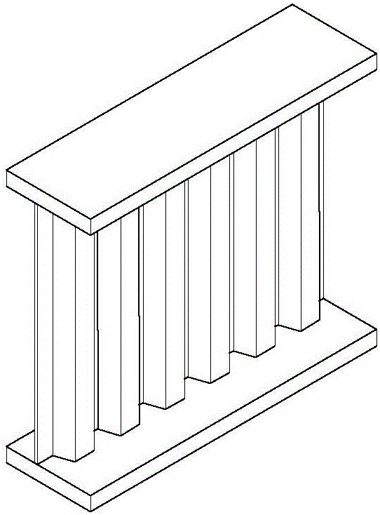
[0065] Such as Figure 15 As shown, the first frame-type composite structure integrated pipe gallery 100 disclosed in the present invention includes unit pipe joints 103 formed by combining unit plates 101 located on the upper and lower sides and side unit plates 102 located on both sides. The plates in the plate are all straight, such as Figure 13 , Figure 14 shown. Wherein, the plates in the unit plates can be arc-shaped or straight plates with small curvature, wherein the arc-shaped plates make the torsional rigidity of the unit plates higher, and the ability to resist vertical instability is stronger. Improve weld quality to a certain extent and reduce stress concentration. When the plate of the lower unit plate is straight, it can be used without paving, and its internal pipeline layout is more convenient, and it can be directly use...


PUM


Abstract

The invention discloses a synthesized pipe rack with a frame composite structure. The synthesized pipe rack comprises unit plate pieces positioned on the upper and lower surfaces, and side unit plate pieces positioned on two side surfaces; the unit plate pieces and the side unit plate pieces are combined and spliced to form unit pipe sections; the unit pipe sections are axially spliced to form the synthesized pipe rack; the unit plate pieces consist of plates, hollow second pipes positioned at two ends, and hollow first pipes positioned at the other two ends; the side unit plate pieces consist of plates, and hollow second pipes positioned at two ends; the second pipes are axial splicing ends of the unit pipe sections; and in splicing of the synthesized pipe rack, the first pipes form longitudinal beams of the synthesized pipe rack, and the adjacent second pipes are connected with each other to form a skeleton structure of the synthesized pipe rack. The longitudinal beams and the skeleton structure of the pipe rack bear main loads; a bridge steel web structure is formed to enhance the shearing resistance of the pipe rack, and is skillfully used; based on dual enhanced structures, the bearing capacity is greatly improved; and under the same filling height, wall plates with the structures are thinner, and materials are saved.

Description

technical field [0001] The invention discloses a comprehensive pipe gallery, in particular to a frame-type composite structure comprehensive pipe gallery. Background technique [0002] At present, most of the urban underground comprehensive pipe gallery is made of reinforced concrete. ~5 meters a joint, the sealing of the joint is a problem, the construction technology requires high requirements, the construction period is long, it is easy to crack and leak during use, the maintenance cost is high, and the entire project uses a large amount of cement, which is not conducive to environmental protection. Among them, the rectangular structure pipes, the walls on both sides, not only bear the vertical load on the upper part, but also bear the lateral load of the side soil layer, and the top plate directly bears the dynamic load and static load, but because only the ordinary Advanced reinforced concrete technology, in order to resist bending moment and bending, enhance its beari...

Claims


Application Information

Patent Timeline
Patent Type & Authority Applications(China)
IPC IPC(8): E02D29/045
CPCE02D29/10
Inventor 战福军
Owner NANJING LIANZHONG CONSTR ENG TECH
Learn More