Combustion gas feeding and ignition device for a gas engine

A technology of gas engine and ignition device, which is applied to gaseous engine fuel, combustion engine, internal combustion piston engine, etc., can solve the problems of pressure rise, inability to prevent fire off, emission, etc., so as to reduce the emission of harmful substances and reduce the main Gas dead zone, optimized combustion effect

Active Publication Date: 2016-08-03
HOERBIGER WIEN GMBH
View PDF12 Cites 8 Cited by
  • Summary
  • Abstract
  • Description
  • Claims
  • Application Information

AI Technical Summary

Problems solved by technology

[0003] The known combustion methods of externally ignited gas engines are all based on the principle of either supplying a combustible mixture to the working chamber during filling of the cylinder during the intake stroke, or forming a combustible mixture in the working chamber by injecting gas during the compression stroke. Then The combustible mixture is ignited by spark ignition or by injecting a small amount of pyrophoric liquid fuel. Here, when ignited, the fuel used for combustion has been mixed with the combustion air. It can be ignited directly in the cylinder, or by igniting in the pre-chamber Indirect ignition by way of ignition. Can be ignited in the pre-chamber by means of spark ignition, which causes a jet of hot gas expelled from the pre-chamber into the main combustion chamber (cylinder), which makes the main combustion chamber The combustible mixture is ignited, and usually a turbulent flame front then passes through the combustible mixture. Through the ignition in the main combustion chamber and the pressure increase thus achieved, the required mechanical useful work is performed by means of the piston during the power stroke. These are very effective and basically All robust combustion methods have disadvantages: they tend to misfire or pre-ignite at unfavorable fuel-air ratios, which can lead to too high emissions of harmful substances, poor efficiency and / or extreme mechanical loads. Fire or pre-ignition will threaten the safe and reliable operation of the gas engine. Rapid load changes may especially cause the above-mentioned adverse changes in the fuel-air ratio. Therefore, the use of gas engines will be limited when the speed of load changes is high.
[0008] In US2,799,255A, the feed of fuel into the pre-chamber and the feed of main fuel into the main chamber are controlled mechanically by means of a cam drive mechanism. Again, the camshaft operates a crank which acts on The valve tappets of the fuel valve and the main fuel valve, wherein the valve tappets are also forcibly synchronized by means of the crank. This determines the supply of fuel or main fuel, as well as the resulting fuel / air mixture and main fuel / air mixture. But Spontaneous ignition due to compression heating cannot be reliably prevented. Misfiring due to too lean a mixture in the pre-chamber cannot be reliably prevented. This can especially be problematic if the supply of fuels of variable quality or main fuel, e.g. natural fuels such as natural gas are completely This may be the case. The way to improve this situation in US2,799,255A is simply to vary the fuel and / or main fuel pressure to achieve the desired match. Due to the inherent inertia of pressure regulation, it may not be possible during rapid load changes The injection is tracked fast enough that reliable ignition cannot be guaranteed, especially at rapid load changes.
[0009] DE 10 2014 000 229 A1 also describes a gas engine using the diffusion combustion method. However, the amount of main fuel for combustion in the main combustion chamber can only be controlled indirectly via a needle valve element, which actuates the needle on the low-pressure side of the needle valve element. Valve element. It is therefore more difficult to control the injection quantity of the main gas and the combustion in the main combustion chamber.

Method used


Image

  • Combustion gas feeding and ignition device for a gas engine
  • Combustion gas feeding and ignition device for a gas engine
  • Combustion gas feeding and ignition device for a gas engine

Examples


Embodiment Construction

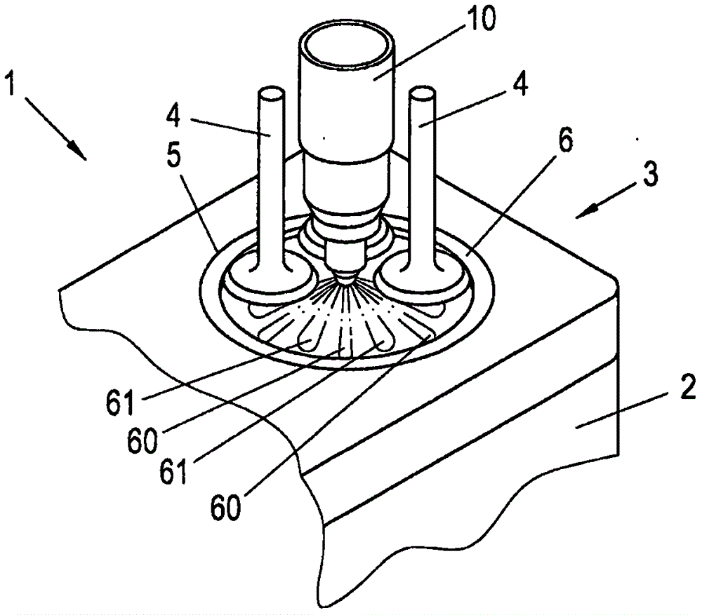
[0033] figure 1 Shown is a part of a gas engine 1 comprising a cylinder block 2 and a only schematically indicated cylinder head 3 and valves 4. A cylinder 5 is arranged in the cylinder block 2 in which a piston 6 can reciprocate. This basic design and function of a piston internal combustion engine is already known, so it will not be described in detail here. In the cylinder head 3 there is also a gas supply and ignition device 10 according to the invention, with which the main gas is supplied and ignited The device is supplied to the main combustion chamber 11 of the cylinder 5, and the gas supply and ignition device is used to ignite combustion in the main combustion chamber 11, which will be described in detail below.

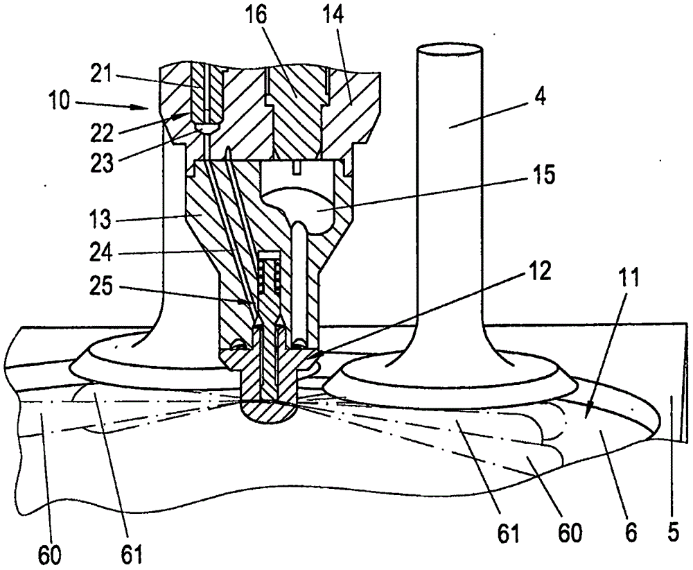
[0034] figure 2 An enlarged sectional view showing the cylinder 5 together with the gas supply and ignition device 10 and its main components. The gas supply and ignition device 10 is arranged in the cylinder head 3 in such a way that it protrudes into t...


PUM


Abstract

For a fuel gas feed and Ignition apparatus for a gas engine (1) with a combustion chamber injection nozzle (12) in which a number of injection channels (37) are provided for a main fuel gas, and the injection channels (37) are connected to a main fuel gas feed line (24) for main fuel gas in which a main fuel gas valve (21) is arranged, and in which combustion chamber injection nozzle (12) are also provided a number of torch channels (52) for hot combustion gas and the torch channels (52) are connected to a pre-combustion chamber (15) in the fuel gas feed and ignition apparatus (10), wherein an ignition fuel supply line (17) leads to the pre-combustion chamber (15) and a pre-combustion chamber valve (18) is arranged in the ignition fuel supply line (17), control of both the time and the duration and thus also the quantity of the injection of main fuel gas, as well as of Ignition fuel for the pre-combustion chamber completely independently of one another and in a precise and, above all, rapid manner is achieved in that both the main fuel gas valve (21) and the pre-combustion chamber valve (18) are embodied as an electrically actuated, electronically controlled valve.

Description

technical field [0001] The invention relates to a gas supply and ignition device for a gas engine having a combustion chamber nozzle in which a certain number of injection channels for the main gas are arranged, and the injection channels are connected to the The main gas supply pipe of the gas is connected, and a certain number of flame passages for hot combustion gas are set in the combustion chamber nozzle, and the flame passages are connected with the pre-combustion chamber in the gas supply and ignition device, and the ignition fuel supply pipe leads to the pre-combustion chamber. In the combustion chamber, and in the ignition fuel supply line, a pre-chamber valve is arranged, which is configured as an electrically operated, electronically controlled valve. Furthermore, the invention relates to a gas engine for operating A method in which air or an air / exhaust gas mixture is compressed in a cylinder of a gas engine during a compression stroke and the compressed air is for...

Claims


Application Information

Patent Timeline
Patent Type & Authority Applications(China)
IPC IPC(8): F02M21/02F02B19/10
CPCF02B19/12F02B19/18F02B43/00F02M21/02F02M21/0275F02B19/108F02M21/0218F02M21/0245F02M21/0251F02M21/0266F02M21/0293F02D19/0642F02M21/0248F02M45/08F02M61/02F02M61/1813Y02T10/12Y02T10/30
Inventor M·肯策尔G·科格勒P·施泰因吕克
Owner HOERBIGER WIEN GMBH
Why Eureka
Try Eureka