Supercharge Your Innovation With Domain-Expert AI Agents!

Multi-hole rectangular waveguide directional coupler

A technology of directional coupler and rectangular waveguide, which is applied in the direction of waveguide devices, electrical components, connecting devices, etc., can solve the problems of reduced directivity, high insertion loss, narrow bandwidth, etc., and achieve directivity optimization, wide working bandwidth, small The effect of insertion loss

Active Publication Date: 2016-08-03
UNIV OF ELECTRONICS SCI & TECH OF CHINA
View PDF3 Cites 12 Cited by
  • Summary
  • Abstract
  • Description
  • Claims
  • Application Information

AI Technical Summary

Problems solved by technology

[0003] The first real directional coupler was designed and implemented by H.A. Wheeler in 1944. Wheeler used a pair of cylinders with a length of a quarter of the center frequency wavelength to achieve mutual coupling of electric and magnetic fields. Unfortunately, this method can only achieve a bandwidth of one octave
[0004] At present, the main directional couplers include microstrip and waveguide directional couplers. However, microstrip lines are not suitable for working in the millimeter wave band due to their large transmission loss. Although non-planar waveguide structures such as dielectric waveguides and rectangular waveguides have small losses and high performance, they are Due to its large size and difficulty in integrated processing, it is difficult to be widely used in highly integrated systems
[0005] The traditional single-hole directional coupler has some advantages: such as simple structure, few parameters, and it is more convenient to design; but it also has some disadvantages: such as narrow bandwidth and poor directivity, it is only suitable for working at the design frequency, and it deviates from this frequency , the directionality will decrease
[0006] Although the traditional porous directional coupler can achieve a wide bandwidth and improve the directivity, it also has some disadvantages, such as large volume, high processing precision requirements, and high insertion loss, especially in the millimeter-wave terahertz band. Excessive insertion loss makes the device useless

Method used


Image

  • Multi-hole rectangular waveguide directional coupler
  • Multi-hole rectangular waveguide directional coupler
  • Multi-hole rectangular waveguide directional coupler

Examples


Embodiment Construction

[0030] The present invention will be further described below in conjunction with accompanying drawing and specific embodiment:

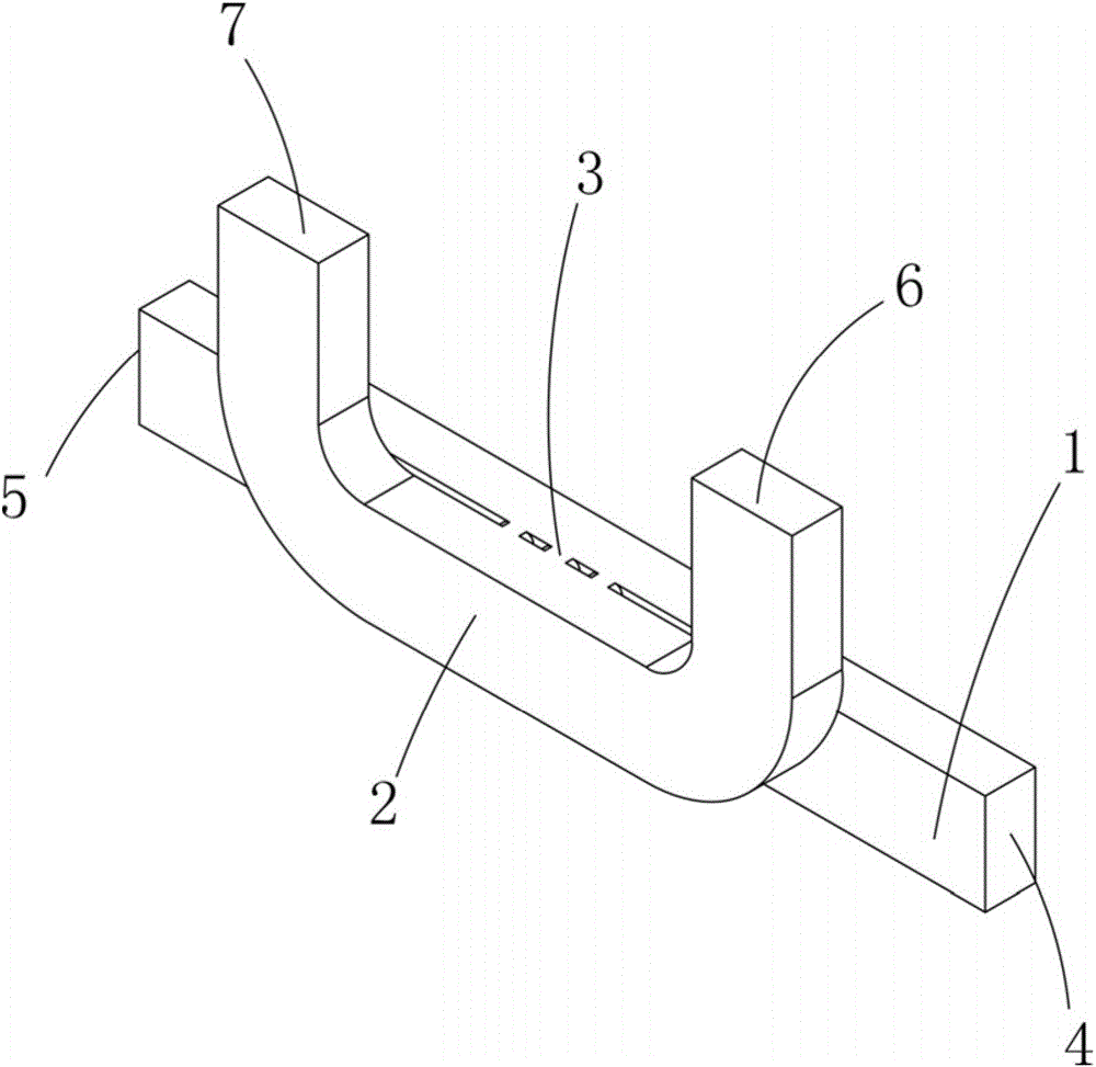
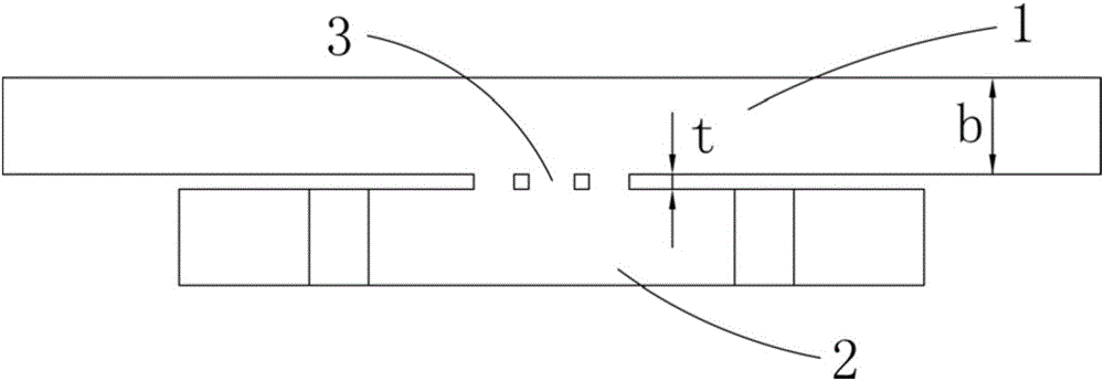
[0031] Such as figure 1 As shown, a kind of porous rectangular waveguide directional coupler of the present invention includes the main rectangular waveguide 1 as the microwave main channel, the secondary rectangular waveguide 2 as the sampling signal channel and the coupling hole 3 as the coupling channel; the main rectangular waveguide 1 of the main The mode H plane and the main mode H plane of the secondary rectangular waveguide 2 are parallel to each other, the main mode H plane mentioned here is the magnetic field plane; the main rectangular waveguide 1 and the sub rectangular waveguide 2 are isolated from each other, and the two are arranged along the axis of the main rectangular waveguide The coupling hole 3 of the main rectangular waveguide 1 is connected; one end of the main rectangular waveguide 1 is the input end 4, and the other end is th...


PUM


Abstract

The invention discloses a multi-hole rectangular waveguide directional coupler. The multi-hole rectangular waveguide directional coupler includes a main rectangular waveguide which is used as a microwave main channel, an auxiliary rectangular waveguide which is used as a sampling signal channel, and coupling holes which are used as the coupling channel, wherein a master mode H plane of the main rectangular waveguide and a master mode H plane of the auxiliary rectangular waveguide are parallel to each other; the main rectangular waveguide and the auxiliary rectangular waveguide are isolated from each other, and are communicated through the coupling holes which are arranged along the axis of the main rectangular waveguide; and the coupling holes include a first row of coupling holes and a second row of coupling holes which are midline-symmetrical in the transmission direction for the wide wall of the main rectangular waveguide. The multi-hole rectangular waveguide directional coupler is simple in structure and is easy for processing; the whole structure of the multi-hole rectangular waveguide directional coupler only has six coupling holes, and can be implemented by means of direct usage of a traditional technology on a cavity; through a simulation test, the multi-hole rectangular waveguide directional coupler has wider operation bandwidth and lower insertion loss; and compared with a traditional waveguide coupler, the multi-hole rectangular waveguide directional coupler has the advantages of being small in volume, being simple in structure, and being able to be conveniently integrated in a high frequency band circuit.

Description

technical field [0001] The invention belongs to the technical field of porous directional couplers, in particular to a porous rectangular waveguide directional coupler coupled by six symmetrical holes. Background technique [0002] The directional coupler is a microwave / millimeter wave component widely used in microwave systems. It is mainly used for signal isolation, separation and mixing; the directional coupler is composed of two transmission lines, coaxial line, rectangular waveguide, circular waveguide , striplines and microstrip lines can all constitute directional couplers; so from the structural point of view, there are many types of directional couplers with great differences, but from the perspective of their coupling mechanism, they are mainly divided into four types, namely, small hole coupling, Parallel coupling, branch coupling and matched double T. [0003] The first real directional coupler was designed and implemented by H.A. Wheeler in 1944. Wheeler used a...

Claims


Application Information

Patent Timeline
Patent Type & Authority Applications(China)
IPC IPC(8): H01P5/18
CPCH01P5/18
Inventor 王志刚杨卅男邓希达汪龙蒋洪福徐锐敏延波
Owner UNIV OF ELECTRONICS SCI & TECH OF CHINA
Features
  • R&D
  • Intellectual Property
  • Life Sciences
  • Materials
  • Tech Scout
  • Unparalleled Data Quality
  • Higher Quality Content
  • 60% Fewer Hallucinations
Learn More